


NE555 Astable Timer: Build a Low-Voltage LED Blinker

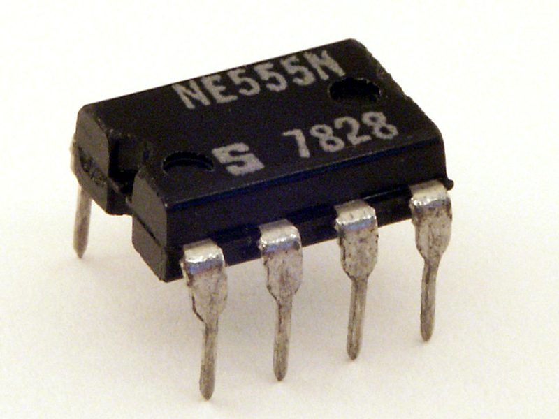
An NE555 astable circuit repeatedly charges and discharges a capacitor to produce a continuous pulse train. It is a useful way to learn timing without a microcontroller. This guide describes a slow, low-voltage LED demonstration based on the standard astable arrangement, with calculated values clearly separated from measured performance.
Start with a complete parts list

Use an 8-pin NE555 suitable for a regulated 5 V supply, RA = 10 kΩ, RB = 68 kΩ and a 10 µF timing capacitor rated above the supply voltage. Also use a 10 nF capacitor for the control-voltage node, a 100 nF local supply bypass capacitor, an LED and a 1 kΩ LED series resistor. Check each part and capacitor polarity before powering. The values are an illustrative design, not a pretested kit guarantee.
Wire the standard astable nodes
| Connection | Wiring for the demonstration |
|---|---|
| Power | Pin 8 to +5 V; pin 1 to GND |
| Reset | Pin 4 to +5 V |
| Timing node | Join pins 2 and 6 |
| RA | 10 kΩ between +5 V and pin 7 |
| RB | 68 kΩ between pin 7 and the joined pins 2/6 |
| Timing capacitor | 10 µF from pins 2/6 to GND, positive at timing node |
| Control bypass | 10 nF from pin 5 to GND |
| Supply bypass | 100 nF between pins 8 and 1 close to IC |
| LED load | Pin 3 through 1 kΩ and LED anode; LED cathode to GND |
Confirm package orientation with the manufacturer pin drawing. Place the IC across the breadboard center gap and verify any split power rails. Perform a short-circuit check only with the supply disconnected.
Calculate the expected period
For the conventional circuit, the approximate high time is 0.693 × (RA + RB) × C, and the low time is 0.693 × RB × C. With the example values, high time is about 0.541 seconds and low time about 0.471 seconds. The approximate total period is 1.012 seconds, or roughly 0.99 Hz. These are calculated nominal values; capacitor tolerance and real device conditions affect the result.
Do not expect an exact 50% duty cycle
The capacitor charges through RA and RB but discharges through RB in this arrangement, so the simple standard circuit does not produce an exact 50% high-time duty cycle with positive RA. Changing the timing network or using another circuit can change that behavior. Do not confuse output-high duty cycle with the discharge-switch duty expression used in some references.
Power up conservatively
Use a current-limited low-voltage bench source and inspect the supply wiring one last time before applying power. The LED should visibly alternate if the circuit is wired and functioning as intended. If there is abnormal heating, disconnect immediately. Do not put the circuit on a high-current battery pack to compensate for a suspected wiring fault.
Diagnose a permanently on or off LED
First check LED polarity and its series resistor, then verify VCC, GND and RESET. Confirm that pins 2 and 6 share the timing node, and that the capacitor is not reversed. A wrong resistor decade can make the pulse too fast to see or much slower than expected. A meter may help identify the supply and slowly changing timing voltage, but an oscilloscope is better for waveform timing if available.Newest in the store


Change one timing component at a time
Increasing C or the timing resistances slows the oscillation. Keep values within the manufacturer’s application guidance; very large resistors and leaky capacitors make timing less predictable. Record the actual component values and any measured period. This simple blinker is not a precision clock or a safety controller, and it should not switch mains or an inductive load directly.
Epro parts and availability
These are relevant Epro listings, not independent authenticity or performance certifications. Prices below were checked on 19 October 2026; they are a dated snapshot rather than a historical price implied by this article’s publication date. Confirm the exact variant, included accessories, stock and current checkout price before ordering.
| Listing | Checked price | Stock at check |
|---|---|---|
| 555 Timer IC NE555 LM555 Timer IC | PKR 14 | In stock |
Frequently asked questions
Is the calculated 0.99 Hz exact?
No. It is a nominal calculation for the stated components. Capacitor tolerance, leakage and real operating conditions affect the period.
Can pin 3 drive a relay directly?
Use an appropriately designed driver and protection circuit for an inductive load. This demonstration only uses a resistor-limited LED.
Related Epro guides
Technical references and verification
The guidance above is based on the manufacturer documentation linked here and the listed product information. Example procedures and sketches are provided for a controlled low-voltage bench setup; no independent hands-on test of your particular board or adapter is claimed. Check the markings and documentation for your actual revision.