


MAX485 Arduino: Two-Node RS485 Wiring and Bring-Up

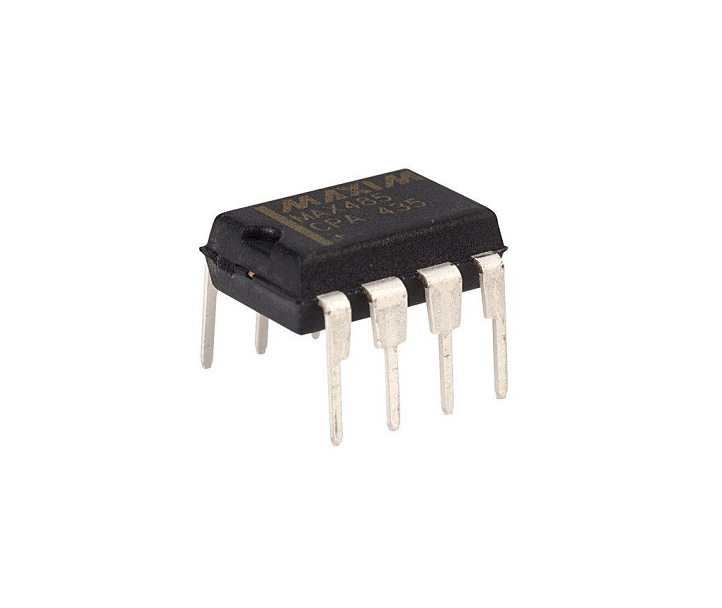
A MAX485 Arduino link can connect two suitable 5 V controllers over a short differential pair. Bring up the physical link with a one-way test before adding replies, addressing or Modbus. This procedure assumes documented transceiver circuits and a controlled bench setup, not an existing industrial network.
Prepare two complete transceiver circuits

Use one MAX485 circuit at each node, each with a correct 5 V supply, local decoupling and the documented pin map. A bare IC listing is not a finished module. Inspect any module’s built-in termination and bias resistors so you know what is already present. Disconnect power before changing the wiring.
Connect UART signals in the correct direction
At each node, host TX drives DI and RO feeds host RX. These are the logic-side connections; they are not the A/B bus wires. Use a UART appropriate to the controller, and keep its programming or USB serial interface separate where possible. A Mega’s additional hardware serial port can simplify this separation compared with sharing the Uno upload UART.
Build a short controlled bus
Connect the documented A terminal to its corresponding differential terminal on the other circuit and likewise for B, plus a suitable signal reference within the permitted common-mode limits. A/B labeling is not perfectly consistent across all vendors; verify the transceiver pin functions and schematic rather than blindly trusting terminal lettering. Use appropriate end termination for the selected cable and test arrangement.
Start with fixed transmit and receive roles
For a one-way check, hold the sending node’s DE high and RE high, so it drives the bus with its local receiver disabled. Hold the receiving node’s DE low and RE low, so it listens without driving. Keep all controls at defined logic levels. This intentionally avoids turnaround timing while the physical connection is being established.
Send a simple repeatable message
Configure both UARTs to the same modest rate, for example 9600 baud with 8 data bits, no parity and one stop bit. Send a short known line once per second from the transmitter and print received bytes through the receiver’s separate diagnostic interface. This is a suggested functional test, not a claim of a measured cable length or error rate.
Add replies only after the one-way link works
For two-way operation each node must release the bus after the last stop bit has physically left the UART, not merely after bytes have entered a software buffer. Check the exact platform’s transmit-complete mechanism. Arrange a clear request/reply schedule so only one driver is enabled. Do not assume that every library’s flush function has identical semantics.
Newest in the store


Diagnose faults by layer
No bytes calls for supply, common reference, RO/DI routing and enable-state checks. Garbled text calls for baud, framing, polarity and signal-integrity checks. A working text link does not prove Modbus framing, addressing or CRC behavior. Keep industrial equipment disconnected until electrical protection, protocol handling and safe failure behavior have been designed and tested.
Relevant Epro listing
Product information and prices were checked on 19 October 2026. This is a current snapshot, not a historical price associated with the publication timestamp. Stock, accessories and checkout prices can change. Listing claims are not independent performance or authenticity certifications.
| Product | Checked price | Stock |
|---|---|---|
| MAX485-RS-485/RS-422 Transceiver IC in Pakistan | PKR 90 | In stock |
Frequently asked questions
Can both nodes keep DE high?
No. That can produce bus contention when they drive different states. Half-duplex operation needs controlled access.
Why use a one-way first test?
It separates basic wiring and UART faults from direction-turnaround and protocol faults.
Related Epro reading
Review breadboard connections before assembling a prototype. For controller expansion, the Mega 2560 pin guide explains why pin names and electrical limits must be checked together.
Technical references and test limitations
This guide uses the documentation linked below. The procedures are for a controlled, low-voltage learning setup; no independent hands-on test of the particular seller board is claimed. Record the actual part markings, wiring and firmware version before drawing conclusions from a test.