


MCP4725 DAC: A Safe First Output-Voltage Test

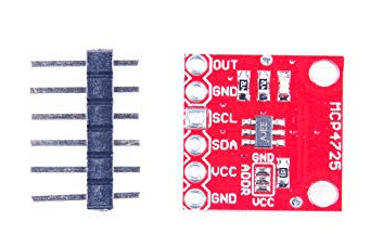
A first MCP4725 test should create a few steady voltages into a high-impedance meter, not immediately drive a consequential control input. This procedure separates communication, ideal scaling and measurement error. It uses ordinary volatile DAC updates so the test does not repeatedly consume EEPROM write cycles.
Prepare a supported supply and I2C bus

Verify the breakout’s supply, ground and SDA/SCL labels. Use a supply within the actual board limits and bus pull-ups compatible with the host. Keep the initial circuit short and connect only the DAC plus a suitable high-impedance voltmeter. Do not attach an external voltage source to VOUT.
Measure the actual reference voltage
Measure VDD at the DAC under the test conditions. The device uses this voltage as its reference, so assuming exactly 5.000 V from a nominal five-volt connector can create a false error diagnosis. Record both the supply reading and meter limitations before evaluating output readings.
Confirm the selected address and write mode
Use the actual address option and A0 setting with a documented MCP4725 driver. Select a DAC-register-only or fast volatile write, not a command that also programs EEPROM. Check the driver’s function arguments: a boolean named writeEEPROM or similar should not be enabled accidentally in a repeatedly executed loop.
Test three widely separated codes
Write codes such as 0, 1024 and 2048, allowing the reading to settle at each step. Ideally 1024 gives one quarter of measured VDD and 2048 gives one half. These are calculated targets, not claimed test results. Near-rail behavior and actual error must be interpreted within the datasheet and the measurement setup.
Separate resolution from observed accuracy
At a measured 3.3 V reference, the ideal step is about 0.806 mV. That calculated increment does not prove that the meter, reference or complete board is accurate to 0.806 mV. Use sensible display precision and compare several codes rather than declaring calibration from one convenient midpoint.
Investigate loading and supply effects
If output changes when a load is attached, check whether its impedance and capacitance are suitable for the DAC. If output follows USB supply variation, remember that VDD is the reference. Do not compensate for a bad circuit by writing a larger code beyond 4095 or by treating the output as a current source.
Newest in the store


Make any retained startup setting deliberate
If the application later needs EEPROM retention, perform a justified nonvolatile write using the documented busy/completion behavior and stable power. Keep repeated signal updates volatile. Power-cycle the system with the downstream load made safe and verify the actual startup output before connecting an actuator or another consequential circuit.
Relevant Epro listing
Product information and prices were checked on 19 October 2026. This is a current snapshot, not a historical price associated with the publication timestamp. Stock, accessories and checkout prices can change. Listing claims are not independent performance or authenticity certifications.
| Product | Checked price | Stock |
|---|---|---|
| MCP4725 I2C Module DAC (Digital to Analog Converter) Module in Pakistan | PKR 1,050 | In stock |
Frequently asked questions
Why does output change when the supply changes?
VDD is the DAC reference, so supply changes can affect output at a fixed code.
Should every output update be saved to EEPROM?
No. Use volatile updates for routine changes; nonvolatile writes are slower and have finite endurance.
Related Epro reading
Review breadboard connections before assembling a prototype. For controller expansion, the Mega 2560 pin guide explains why pin names and electrical limits must be checked together.
Technical references and test limitations
This guide uses the documentation linked below. The procedures are for a controlled, low-voltage learning setup; no independent hands-on test of the particular seller board is claimed. Record the actual part markings, wiring and firmware version before drawing conclusions from a test.