


TMP102 Temperature Sensor: 7 Format and Accuracy Checks

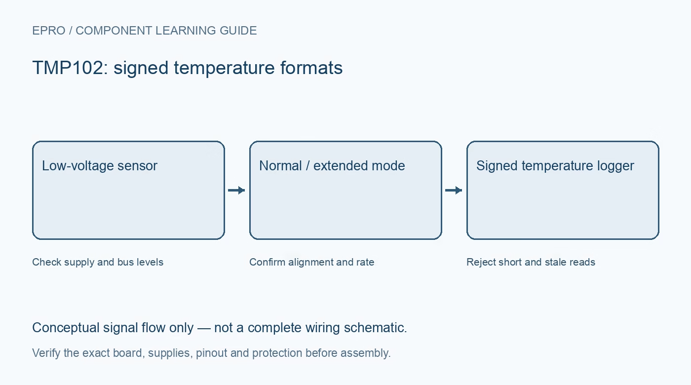
A TMP102 can provide compact low-voltage temperature monitoring, but its register format and accuracy limits need careful reading. Select it against the requirements of the complete installation rather than assuming every small I2C temperature board has the same precision.
Read the guaranteed error limits
The 0.0625 degree Celsius output step is not the guaranteed absolute accuracy. The referenced TMP102 datasheet lists maximum error limits that differ from the typical headline figure. Use the limit for the intended temperature interval and do not borrow the tighter specification of another TI part.
Match the low-voltage supply
The device operates from 1.4 to 3.6 V. A bare sensor is therefore not a 5 V supply component. A breakout may add regulation or translation, but verify both functions separately from its schematic before connecting it to a 5 V microcontroller.
Choose normal or extended mode deliberately
Normal operation uses a twelve-bit signed result, while extended mode changes the meaningful field to thirteen bits and changes its alignment. Confirm that the driver and application agree on the mode; the same raw word decoded with the wrong shift can produce a convincing but wrong temperature.
Separate conversion rate from conversion time
Selectable conversion rates include 0.25, 1, 4 and 8 conversions per second. The time required for an individual conversion is a different quantity from the interval between scheduled results. Reading the register hundreds of times per second cannot create hundreds of independent observations.
Plan the address connection
The address input supports documented wiring options, including connections beyond simply ground or supply. Follow the exact table rather than guessing a binary strap scheme. Confirm that carrier solder bridges implement the desired option and that no other device already uses the resulting address.
Check the alert role and thresholds
The ALERT output can behave differently in comparator and interrupt modes. Polarity, fault queue and threshold representation all matter. Threshold registers must be interpreted consistently with extended-mode selection; a room-temperature test should not unexpectedly use a value encoded for another format.
Newest in the store


Account for installation heating
The sensor observes its own package temperature, influenced by the board and enclosure. Keep it away from heat-producing parts and allow settling before comparison. This learning module is not automatically a calibrated clinical thermometer or an independent overtemperature safety device.
Frequently asked questions
Can a TMP102 be powered directly from 5 V?
Not as a bare component; its stated supply ceiling is 3.6 V. Verify any carrier regulation and logic translation.
Does extended mode improve the temperature step?
It changes the signed range and alignment, not the basic 0.0625 degree step.
Availability and illustration note
No matching Epro product was returned by the catalog search on 21 October 2026 UTC. This learning guide does not assert stock, a selling price or compatibility of an unidentified substitute. The illustration is an original conceptual signal-flow diagram, not a product photograph or complete wiring schematic.
Related Epro reading
For a first bench setup, review breadboard connections and continuity checks and I2C voltage-level translation. These guides do not replace the exact module schematic.
Technical references and limitations
Source: Texas Instruments TMP102 datasheet. Electrical limits apply to the named part, not automatically to every carrier board. This is a documentation-based learning workflow, not a claim of independent hardware testing, traceable calibration or safety certification.