


BC547 Transistor as a Switch: Wiring and Voltage Checks

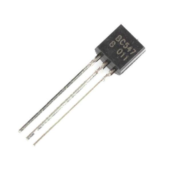
A BC547 transistor as a switch can control a small LED load while keeping load current out of the control contact or signal pin. This guide emphasizes checking the actual on/off voltages and resistor currents. It is a low-voltage learning circuit, not a ready-made relay, mains or motor interface.
Map collector, base and emitter correctly

Confirm the supplied device’s full marking and package drawing before wiring. Use pin functions rather than a generic flat-face rule. With power removed, connect the emitter to the circuit return and put a suitable resistor-limited LED between the positive low-voltage supply and collector. Check LED polarity and breadboard rail breaks.
Choose the load current first
Select a modest indicator current and calculate its series resistor using supply, LED forward voltage and a conservative allowance for the transistor’s on-state voltage. For example, a five-volt source and a 2.2 kohm LED resistor produce only a small current with a normal indicator LED. Measure the resistor drop to find the actual current instead of reporting a guessed fixed value.
Limit base current independently
Use a base resistor selected for the control voltage and intended collector current while staying inside the source’s output capability. A base-to-emitter resistor can define off behavior when the control is disconnected. Do not assume the LED resistor also limits base current; these are different circuit paths with different jobs.
Verify the off state
With the control inactive, check that base drive is removed and the LED is off. A floating base, an unexpected pull-up or a swapped transistor lead can cause leakage-like behavior. Label the common reference for all voltage measurements. If the circuit depends on a microcontroller, include its reset and unpowered states in the reasoning.
Measure the on state and understand saturation
With intended drive applied, measure collector-to-emitter voltage and load-resistor drop. A suitably designed low-current switch should have an on-state consistent with its datasheet conditions, but no single typical value applies to every load and grade. An unexpectedly large collector drop can indicate insufficient base drive, excessive load or incorrect wiring.
Check heat and power rather than only light
An illuminated LED does not prove the transistor is operating safely. Estimate transistor dissipation from its actual collector current and collector-emitter voltage, and check the selected device’s thermal limits. In this modest demonstration abnormal heating is a reason to stop and inspect. Do not increase current to reproduce a maximum-rating number.
Newest in the store


Redesign before changing the load type
An inductive coil needs an appropriate transient path and load-current analysis. A higher-current lamp can have startup current well above its steady value. A logic-level MOSFET or a dedicated driver may be a better choice for another application. Keep the conclusions from this test limited to its actual LED load and drive arrangement.
Relevant Epro listing
Product information and prices were checked on 19 October 2026. This is a current snapshot, not a historical price associated with the publication timestamp. Stock, accessories and checkout prices can change. Listing claims are not independent performance or authenticity certifications.
| Product | Checked price | Stock |
|---|---|---|
| BC547 NPN Bi-polar Junction Transistor in Pakistan | PKR 8 | In stock |
Frequently asked questions
Why can an LED light even when the transistor is not a good switch?
The device may still conduct with excessive voltage drop or incorrect bias. Measure current and on-state voltage, not only visible light.
Can the same resistor values drive every load?
No. Recalculate from supply, load, drive and device conditions, and redesign protection for other load types.
Related Epro reading
Review breadboard connections before assembling a prototype. For controller expansion, the Mega 2560 pin guide explains why pin names and electrical limits must be checked together.
Technical references and test limitations
This guide uses the documentation linked below. The procedures are for a controlled, low-voltage learning setup; no independent hands-on test of the particular seller board is claimed. Record the actual part markings, wiring and firmware version before drawing conclusions from a test.