


MCP3008 Raspberry Pi: A 3.3V Potentiometer Input Test

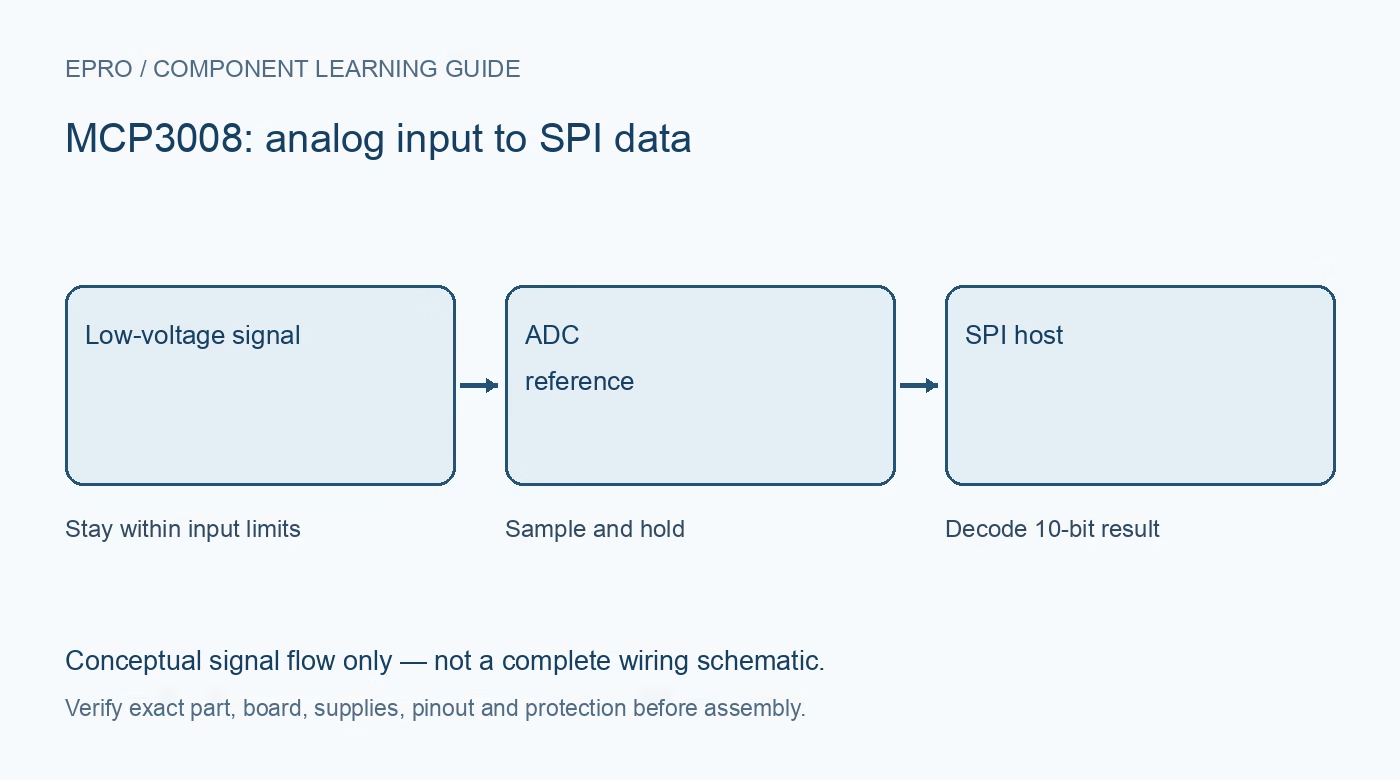
An MCP3008 Raspberry Pi test can begin with a potentiometer referenced to the same 3.3 V rail as the ADC. The goal is to verify wiring, channel selection and scaling with a known bounded source before connecting an unknown sensor.
Match the physical package drawing
For the documented 16-pin MCP3008 package, channels 0–7 occupy pins 1–8, followed by digital ground 9, chip select 10, DIN 11, DOUT 12, clock 13, analog ground 14, VREF 15 and VDD 16. Confirm the exact part, orientation and board adapter before applying these assignments. Raspberry Pi physical header numbers are not the same as GPIO identifiers.
Keep the complete interface at compatible levels
Use an appropriate 3.3 V supply arrangement for the ADC and reference in this example, with grounds connected as intended and local bypassing following the datasheet. Connect Pi MOSI to ADC DIN, Pi MISO to ADC DOUT, clock to clock and the selected chip-enable signal to chip select. Never apply a 5 V peripheral output to a Pi GPIO.
Create a bounded analog input
Connect the two outer terminals of an illustrative 10k potentiometer between the ADC reference rail and analog ground, with the wiper to channel 0. Check its wiper voltage with a meter before the ADC connection. Use conservative SPI timing and consider the datasheet source-impedance guidance; a pot test is not a universal front end for all sensors.
Enable SPI and choose a documented driver
Enable the appropriate SPI interface in the operating system and use a maintained MCP3008 driver or a transaction implementation checked against the datasheet. Record bus number, device select, mode and clock. If permission or device-file errors occur, solve those host issues separately rather than changing analog wiring at random.
Check raw codes before converting to volts
Log the ten-bit raw result while moving the potentiometer slowly through its range. Expect a trend toward the low and high codes, allowing for real reference and converter errors. For an ideal unipolar scale, one step is VREF divided by 1024. Use the measured reference in voltage estimates and recognize that the highest code is not a separate exact measurement of the supply.
Test symptoms systematically
A fixed zero may indicate input, channel or serial-path errors; a fixed full-scale reading may indicate a high input or decoding problem. Compare channel 0 with a known ground input and a measured intermediate voltage. Inspect SPI selection and ground before blaming the sensor. Do not infer an exact calibration from the same rail powering both the reference and potentiometer.Newest in the store


Availability and illustration note
No matching product was found in the checked Epro catalog for this topic on 19 October 2026. This article therefore does not quote an Epro price or claim stock. The original illustration shows conceptual signal flow only, not a complete circuit or a photograph of a supplied product. Obtain a documented component or carrier with a known pinout and electrical specification.
Frequently asked questions
Can the ADC be powered at 5 V without level adaptation to Pi?
Do not assume that is safe or logically compatible. This example keeps the interface at 3.3 V and still requires checking the complete specification.
Why keep raw counts in the test log?
They help distinguish decoding and channel problems from reference-voltage or display-scaling errors.
Related Epro reading
Review breadboard connections before assembling a prototype. For controller expansion, the Mega 2560 pin guide explains why pin names and electrical limits must be checked together.
Technical references and test limitations
This guide uses the documentation linked below. The procedures are for a controlled, low-voltage learning setup; no independent hands-on test of the particular seller board is claimed. Record the actual part markings, wiring and firmware version before drawing conclusions from a test.