


MCP7940N RTC: 7 Backup and Power-Fail Evidence Checks

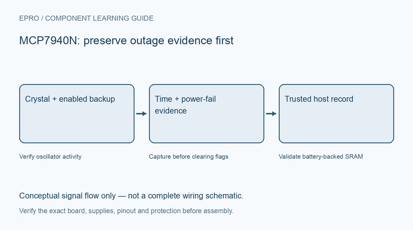
An MCP7940N combines calendar timekeeping, alarms, power-fail evidence and sixty-four bytes of battery-backed SRAM. Its useful retention features require the correct crystal and backup configuration. Verify the exact carrier and documented register behavior before selecting it for a low-voltage logging project.
Check the oscillator and board layout
The device uses an external 32.768 kHz crystal or its documented external-clock arrangement. Confirm the crystal specification, loading and layout rather than assuming an RTC IC alone guarantees accurate time. Carrier contamination, routing and unsuitable components can affect startup or drift even when I2C communication works.
Verify main and backup supply conditions
Read the voltage requirements for the intended interface and backup modes. Check the actual backup source, polarity and carrier circuitry. The VBAT pin is a backup supply input, not permission to charge a primary cell or connect an arbitrary higher-voltage battery.
Enable backup intentionally
The VBATEN bit must be set for the backup input to support retention as documented. Installing a battery without checking that bit is not a complete backup design. If backup is unused, follow the manufacturer’s pin-connection guidance instead of leaving the supply arrangement unspecified.
Distinguish start control from running status
The ST control enables the crystal oscillator, while OSCRUN reports detected oscillator activity after its documented interval. A set status bit does not prove the frequency is perfectly accurate or that calendar time was initialized correctly. Check both control intent and actual activity before accepting timestamps.
Preserve power-fail evidence before clearing
The PWRFAIL flag and associated registers record primary-supply loss and restoration. Clearing the flag clears timestamp evidence, and writing the weekday register also has a documented clearing side effect. Capture the records before initialization routines overwrite them if outage history matters to the application.
Treat SRAM as battery-backed, not EEPROM
The sixty-four-byte user SRAM retains contents only with valid supporting power and configuration. It is not an independently nonvolatile EEPROM. Its power-on contents are not a trustworthy initialized record. Use a signature, version and integrity check before accepting application state stored there.
Newest in the store


Specify a complete acceptance test
Initialize trusted time, verify advancing seconds and then test a documented backup transition. Capture power-fail records and validate SRAM after main power returns, before clearing status. Crystal trimming requires meaningful reference measurements; these integration checks do not establish calibrated timekeeping, guaranteed cell life or certified outage logging.
Frequently asked questions
Does VBATEN matter if the backup battery is installed?
Yes. The documented backup input must be enabled for the intended retention behavior.
Are the sixty-four SRAM bytes permanent without any supply?
No. They require valid supporting power; treat undefined or unvalidated contents as invalid.
Availability and illustration note
No matching Epro product was returned by the catalog search on 21 October 2026 UTC. This learning guide does not assert stock, a selling price or compatibility of an unidentified substitute. The illustration is an original conceptual signal-flow diagram, not a product photograph or complete wiring schematic.
Related Epro reading
For a first bench setup, review breadboard connections and continuity checks and I2C voltage-level translation. These guides do not replace the exact module schematic.
Technical references and limitations
Source: Microchip MCP7940N Revision H datasheet. Electrical limits apply to the named part, not automatically to every carrier board. This is a documentation-based learning workflow, not a claim of independent hardware testing, traceable calibration or safety certification.