


A3144 Hall Effect Sensor: Open-Collector Output and Part Identity

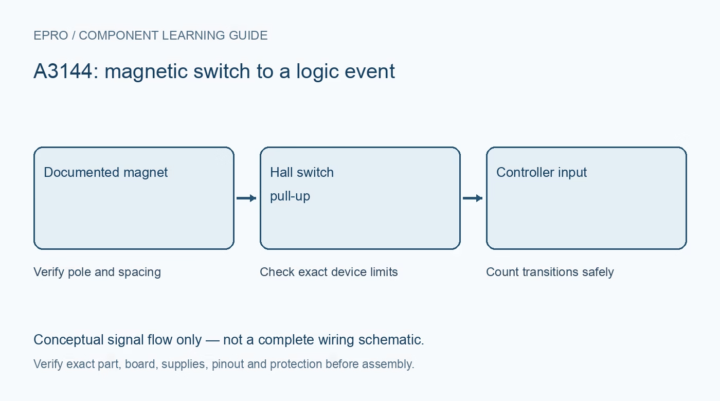
An A3144 Hall effect sensor is a magnetic switch, not an analog magnetic-field meter. Its output needs a suitable pull-up and a known electrical reference. Because the original Allegro family documentation is marked discontinued, verify the actual manufacturer and marking of any current part sold under this familiar number.
Check the actual device, not only the sales name
The linked Allegro A3141–A3144 reference is explicitly marked as a discontinued product. A present-day component may come from another manufacturer or be sold using a similar generic designation. Do not assume the old Allegro datasheet certifies an unknown 3144-marked part. Obtain matching supply, pinout, threshold and temperature specifications.
Understand the switched output
The original reference describes an open-collector output. With an appropriate pull-up, the circuit reports a logic state that changes at magnetic operating and release thresholds. It does not produce a proportional analog voltage representing field strength. The pull-up, receiving input and sensor output limits must be compatible.
Separate supply voltage from output pull-up voltage
The original family is specified for a 4.5–24 V operating supply, but that is not a universal specification for every clone or complete module. An open-collector arrangement can permit a separately chosen compatible pull-up voltage if the exact output specification allows it. A module may already tie a pull-up to its own supply, so inspect the carrier before connecting a lower-voltage GPIO.
Select magnet pole and spacing deliberately
A magnetic switch has polarity and threshold behavior that must be matched to the documented sensing face. Test by presenting the appropriate pole at a controlled distance and observing operation and release. Do not infer a precise activation distance from the part number alone: magnet geometry, strength, alignment and nearby material affect the result.
Keep mounting repeatable
Secure the magnet and sensor mechanically so their gap and orientation do not change unpredictably. Avoid exposing a loose magnet near moving machinery during a first test. Repeat the approach and withdrawal slowly before using the switch to count rotation. A digital transition provides a detection event, not an absolute shaft angle.
Choose a supported part for new requirements
For a new product, consider a currently supported magnetic switch with documented thresholds, supply and package. Match unipolar, bipolar or latch behavior to the application rather than substituting only by pin count. This guide does not establish authenticity, precision speed sensing or safety-interlock suitability for an unknown legacy-labelled part.Newest in the store


Availability and illustration note
No matching product was found in the checked Epro catalog for this topic on 19 October 2026. This article therefore does not quote an Epro price or claim stock. The original illustration shows conceptual signal flow only, not a complete circuit or a photograph of a supplied product. Obtain a documented component or carrier with a known pinout and electrical specification.
Frequently asked questions
Does A3144 provide an analog field-strength reading?
The referenced device is a magnetic switch with an open-collector output, not a proportional field sensor.
Can every 3144-labelled part use the Allegro specifications?
No. Verify the actual manufacturer and matching documentation, especially for present-day substitutes.
Related Epro reading
Review breadboard connections before assembling a prototype. For controller expansion, the Mega 2560 pin guide explains why pin names and electrical limits must be checked together.
Technical references and test limitations
This guide uses the documentation linked below. The procedures are for a controlled, low-voltage learning setup; no independent hands-on test of the particular seller board is claimed. Record the actual part markings, wiring and firmware version before drawing conclusions from a test.