


VCNL4010 Proximity Sensor: 7 Counts and Optical Checks

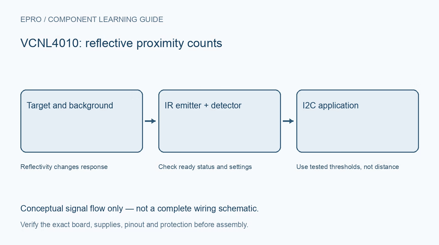
A VCNL4010 integrates an infrared emitter, a proximity measurement function and an ambient-light sensor. It can simplify a reflective detection project, but its proximity count should not be mistaken for a target-independent distance measurement.
Separate the two measurement outputs
Ambient-light and proximity measurements answer different questions. The ambient-light channel has a documented illuminance scaling, while proximity is a reflected infrared response. Do not use the lux conversion for proximity data or label an uncalibrated count as centimetres.
Check the carrier’s power routing
Identify the sensor supply, emitter supply and bus pull-ups from the exact carrier. The emitter operates in pulses, so average current alone is not a complete supply requirement. Verify decoupling and the board’s intended connection rather than powering an unidentified module from an arbitrary GPIO output.
Treat range claims as conditional
The datasheet illustrates response with specified targets, LED current and geometry. Dark fabric, a shiny angled surface and a light matte card can produce very different counts at the same separation. Build an acceptance test around the actual object and enclosure instead of importing a universal range number.
Choose emitter current thoughtfully
The documented LED setting uses 10 mA steps up to 200 mA. Increasing current can change signal level and power demand, but does not remove crosstalk or make a reflective detector a time-of-flight instrument. Start from a documented conservative configuration and change one setting at a time.
Evaluate the optical window and baseline
Cover material and internal reflections can create a response even with no intended target. Measure an empty-scene baseline in the final geometry, then repeat with representative targets. Keep emitter and receiver paths consistent and avoid interpreting an enclosure-reflection offset as a nearby object.
Plan sampling and threshold persistence
Ambient-light averaging and measurement rates affect latency and power. A single threshold sample can chatter around a boundary. Decide on separate enter and leave thresholds or persistence in software, and measure the resulting response time before attaching the detection event to application behaviour.
Newest in the store


Set realistic reliability requirements
Record the expected targets, lighting, geometry, current setting and failure response. Include no-target and out-of-range conditions in testing. This is a reflective sensing component, not a safety-rated human detector, collision-prevention system or guarantee that every dark or transparent obstacle will be detected.
Frequently asked questions
Does a larger proximity count always mean the target is closer?
For an unchanged target and setup it may be useful, but reflectivity, angle and optical crosstalk also affect the response.
Should I immediately use the maximum LED setting?
No. Match the configuration to the board, power supply and measurement objective; higher current is not a substitute for sound optical design.
Availability and illustration note
No matching Epro product was returned by the catalog search on 19 October 2026. This learning guide does not assert stock, a selling price or compatibility of an unidentified substitute. The illustration is an original conceptual signal-flow diagram, not a product photograph or complete wiring schematic.
Related Epro reading
For a first bench setup, review breadboard connections and continuity checks and I2C voltage-level translation. These guides do not replace the exact module schematic.
Technical references and limitations
Source: Vishay VCNL4010 datasheet. Electrical limits apply to the named part, not automatically to every carrier board. This is a documentation-based learning workflow, not a claim of independent hardware testing, traceable calibration or safety certification.