


MCP3208 Arduino: 7 SPI Frame and Channel Checks

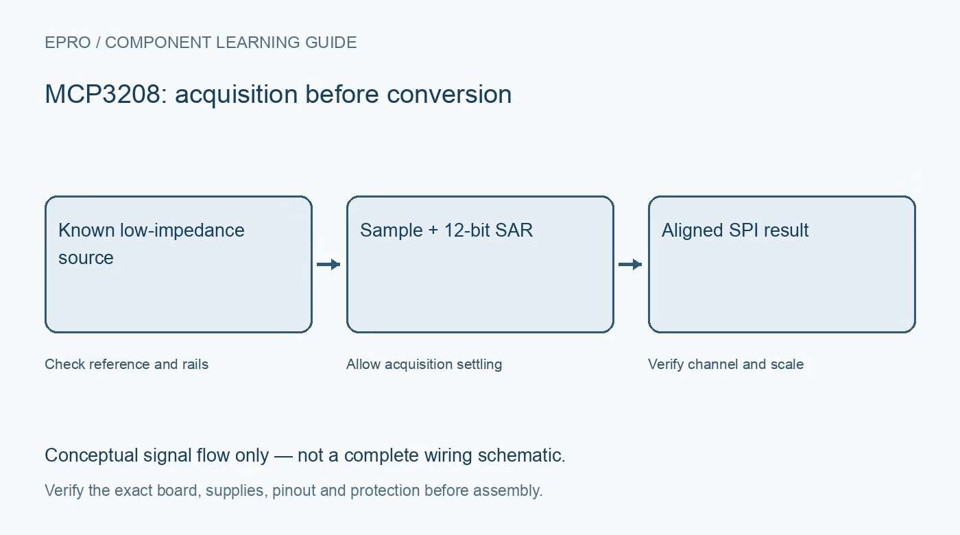
A successful MCP3208 Arduino test distinguishes a valid twelve-bit reading from a convenient-looking serial number. Start with one safe known voltage and a documented reference. Expand to multiple channels only after communication, alignment and acquisition behavior are understood for the actual wiring and clock setting.
Write down the pin and voltage map
Verify the exact package or carrier and identify supply, reference, analog ground, digital ground and SPI pins. Check host pin numbering independently. Use a planned common return rather than treating the two ground labels as permission to leave one disconnected or create an uncontrolled isolated analog domain.
Select a supported SPI mode
The device supports the documented mode-zero or mode-three clock relationships. Use a maintained MCP3208-compatible driver with the intended mode and clock limits for the supply voltage. Initialize chip select to its inactive state before traffic and prevent other devices from driving the shared return line simultaneously.
Inspect the command and result frame
A transaction includes a start bit, single-ended or differential selection, channel selection and the conversion response. The leading null and placement of result bits must be handled correctly. Avoid reusing a ten-bit MCP3008 mask or shift merely because the parts have similarly named interfaces.
Verify twelve-bit scaling explicitly
A valid unsigned single-ended conversion spans the documented twelve-bit code range. Scale using the actual reference and the appropriate ideal step rather than assuming five volts from an Arduino board name. Preserve raw codes alongside calculated voltage so a gain or bit-alignment error remains visible during diagnosis.
Change one channel at a time
Connect two known safe inputs with distinct levels and check that channel selection follows the expected input. Respect the acquisition interval and source impedance after changes. If a high-impedance source is used, evaluate a proper input network rather than relying on repeated reads as an unexplained universal fix.
Test boundaries without exceeding ratings
Check a safe near-ground point and a safe point below the reference, then confirm the ordering and approximate scale. Do not use negative voltages or a higher supply to manufacture endpoint codes. Pseudo-differential configurations require their own restricted negative-input arrangement, not unrestricted bipolar probing.
Newest in the store


Keep timing and recovery observable
Record the clock, reference and selected channel with the result. Treat short transfers and driver errors as unavailable observations rather than zero volts. After restoring a deliberately incorrect software configuration, confirm fresh channel-dependent values return. This verifies integration behavior, not traceable absolute accuracy or protective-system performance.
Frequently asked questions
Why does every channel show the same value?
Check the command channel bits, actual wiring, source settling and any cached driver result.
Can the slowest possible clock always improve accuracy?
No. Follow both maximum and minimum timing constraints in the converter documentation.
Availability and illustration note
The catalog search on 21 October 2026 UTC returned ADC MCP3208 8 Channel 12 Bit Analog To Digital IC. Verify the exact fitted part, carrier schematic, included accessories, current price and availability before ordering; this guide does not establish compatibility from a product title alone. The illustration is an original conceptual signal-flow diagram, not a product photograph or complete wiring schematic.
Related Epro reading
For a first bench setup, review breadboard connections and continuity checks and I2C voltage-level translation. These guides do not replace the exact module schematic.
Technical references and limitations
Source: Microchip MCP3204/3208 datasheet. Electrical limits apply to the named part, not automatically to every carrier board. This is a documentation-based learning workflow, not a claim of independent hardware testing, traceable calibration or safety certification.