


MCP41010 Digital Pot: 7 Terminal and Startup Checks

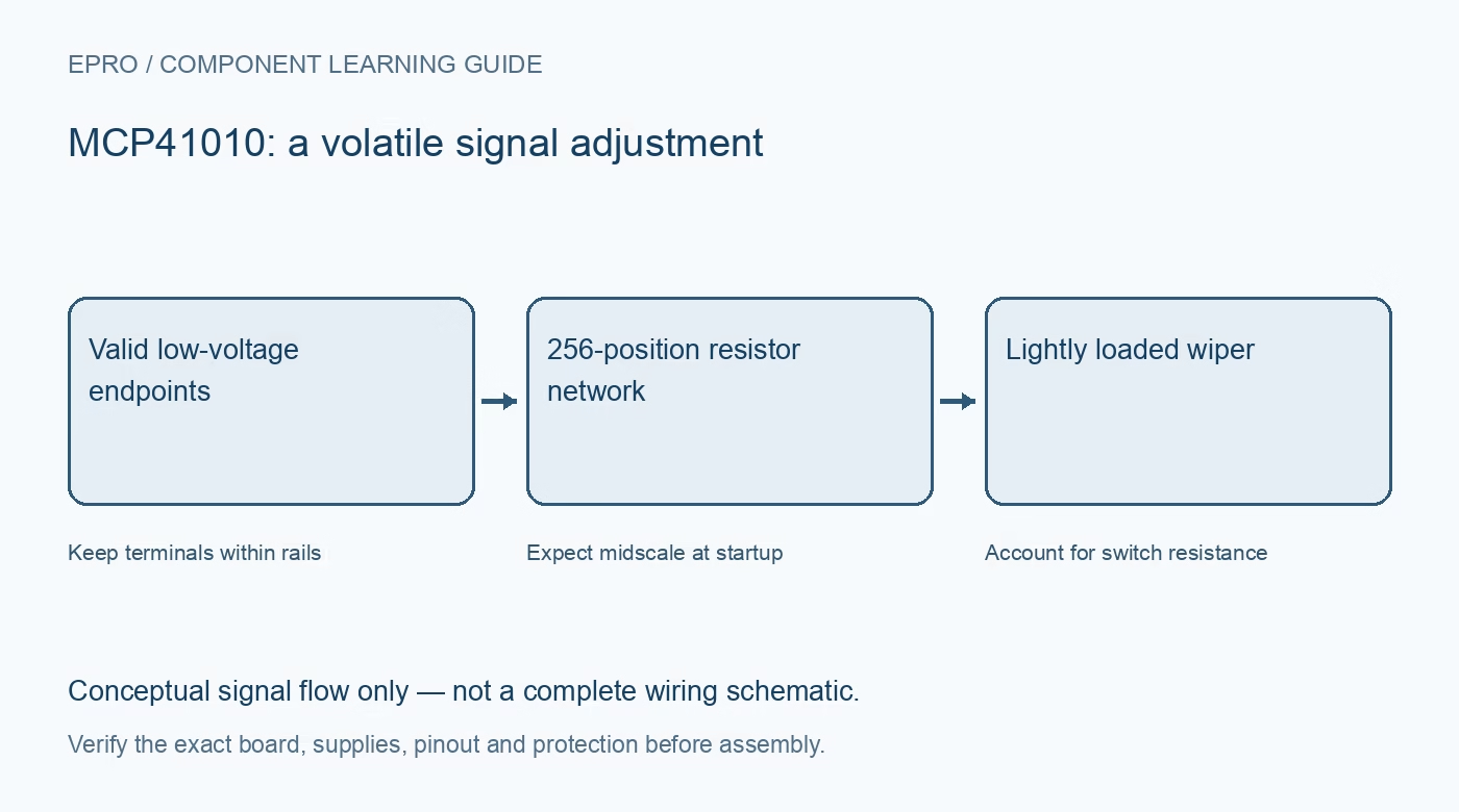
An MCP41010 provides one digitally adjusted resistance network with a nominal ten-kilohm end-to-end value. It can set a low-voltage divider or suitable signal adjustment, but it is not a power rheostat. Check the complete circuit before replacing a mechanical potentiometer or choosing an unidentified module.
Identify the single-channel part
The manufacturer document covers both MCP41XXX single-channel and MCP42XXX dual-channel devices. Their pins and features are not identical. MCP41010 does not acquire the dual device’s serial output, daisy-chain support or extra hardware control pins merely because a shared datasheet describes those functions.
Match supply and control thresholds
The specified supply range is 2.7 V to 5.5 V. Digital input thresholds depend on the supply, so a lower-voltage host is not automatically compatible with a higher-voltage-powered potentiometer. Verify chip select, clock and data levels before connecting the controller, and provide the documented local supply decoupling.
Keep analog terminals inside the rails
The A, B and wiper terminals must remain between ground and the device supply during normal operation. The ability to exchange endpoint polarity does not permit a negative signal or an external higher voltage. Consider power sequencing too: an active external signal must not overdrive an unpowered device.
Include wiper resistance and loading
The wiper is connected through a real switch resistance rather than an ideal short. Loading changes divider behavior, especially near an endpoint. Check specified current and power limits for the intended setting. Use a properly designed buffer when needed instead of driving a speaker, motor or other power load directly.
Distinguish positions from exact resistance
The eight-bit register selects 256 positions. End-to-end tolerance, wiper resistance and loading mean a requested code is not an exact calibrated resistance. A divider ratio and a two-terminal rheostat configuration also have different error behavior. Evaluate the actual configuration rather than assuming a universal ohms-per-code relationship.
Plan for volatile midscale startup
The wiper register returns to midscale, hexadecimal 80, at power-up. It does not remember the last adjustment through a complete loss of supply. If the surrounding circuit needs a different safe startup state, design for the interval before software writes the desired code; saved host preferences alone do not control that interval.
Newest in the store


Define a signal-level acceptance test
Start with a safe divider and a compatible high-impedance measurement. Check several codes for the expected direction and plausible progression, then verify startup behavior. These observations do not certify absolute resistance, precision voltage generation or a fail-safe response. Keep hazardous voltages and unknown power circuits outside this learning setup.
Frequently asked questions
Does MCP41010 retain its last wiper code without power?
No. Its volatile wiper register starts at midscale after power-up.
Can it replace any ten-kilohm mechanical potentiometer?
No. Terminal voltage, current, loading, startup and bandwidth must all suit the circuit.
Availability and illustration note
No matching Epro product was returned by the catalog search on 21 October 2026 UTC. This learning guide does not assert stock, a selling price or compatibility of an unidentified substitute. The illustration is an original conceptual signal-flow diagram, not a product photograph or complete wiring schematic.
Related Epro reading
For a first bench setup, review breadboard connections and continuity checks and I2C voltage-level translation. These guides do not replace the exact module schematic.
Technical references and limitations
Source: Microchip MCP41XXX/42XXX digital potentiometer datasheet. Electrical limits apply to the named part, not automatically to every carrier board. This is a documentation-based learning workflow, not a claim of independent hardware testing, traceable calibration or safety certification.