


BTS7960 Motor Driver: Why the Module Is Not Simply a 43A Switch

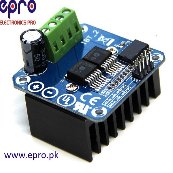
A BTS7960 motor driver board is often advertised around a large current figure, but the chip, complete module and installed wiring have different limits. Select the board from the motor’s supply and startup demand, then evaluate connectors, cooling and protection rather than treating 43A as an unconditional continuous rating.
Separate the IC from the bridge board

Infineon documents the BTS7960 as a protected power half bridge. A typical IBT2-style full-bridge module uses two power devices plus its own connectors and input circuitry. The IC datasheet describes the component; it does not certify every third-party board layout, heatsink, terminal block or supplied device as meeting an advertised module rating.
Start with motor stall and supply behavior
Find the motor’s rated voltage, no-load current and stall or startup demand from credible documentation. A current-limited bench supply may behave differently from a battery. Do not deliberately stall a motor as a casual measurement method. Include fuse selection, wire size, connector capability and mechanical protection in the system design before connecting a high-energy source.
Treat heat as a design constraint
Semiconductor losses, PCB copper, thermal interfaces and airflow all influence continuous operation. A heatsink photograph or one brief unloaded run does not establish sustained load capacity. If temperature rises unexpectedly, stop and investigate rather than depending on repeated thermal shutdown. Protective features are fault responses, not normal operating controls.
Identify power and logic connectors
Typical modules separate motor supply terminals, motor output terminals and a logic header. Follow the actual board labels and schematic, not a generic header position drawing. Confirm logic supply and input thresholds, and understand how enable and PWM signals are routed to the two halves. Current-sense labels are not automatically calibrated analog current readings.
Define safe startup and reversal
Keep drive disabled during controller reset and initialization. Establish the module’s actual coast, brake and disabled states from its circuit before commanding motion. Remove drive and let the mechanical system stop before a basic direction reversal. Rapid reversing can create large current and mechanical shock even if the electronics appear to respond normally.
Buy for a documented application
Compare the actual module, documentation, connector quality and cooling plan against the intended small prototype. If the application approaches high currents or has hazardous movement, use a professionally engineered drive system and risk assessment. The linked Epro listing is a sales option, not independent verification of a safe continuous current in your enclosure.Newest in the store


Relevant Epro listing
Product information and prices were checked on 19 October 2026. This is a current snapshot, not a historical price associated with the publication timestamp. Stock, accessories and checkout prices can change. Listing claims are not independent performance or authenticity certifications.
| Product | Checked price | Stock |
|---|---|---|
| 43A H Bridge Drive PWM BTS7960B IBT2 in Pakistan | PKR 1,490 | In stock |
Frequently asked questions
Is 43A guaranteed continuously on every IBT2 module?
No. Actual limits depend on the complete board, cooling, connectors and operating conditions.
Can thermal shutdown be used to regulate normal loading?
No. A protective shutdown indicates a fault or excessive stress that needs investigation.
Related Epro reading
Review breadboard connections before assembling a prototype. For controller expansion, the Mega 2560 pin guide explains why pin names and electrical limits must be checked together.
Technical references and test limitations
This guide uses the documentation linked below. The procedures are for a controlled, low-voltage learning setup; no independent hands-on test of the particular seller board is claimed. Record the actual part markings, wiring and firmware version before drawing conclusions from a test.