


74LVC245 Bus Transceiver: 7 Supply and Direction Checks

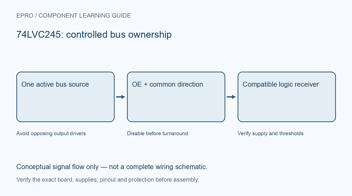
This guide uses the TI SN74LVC245A, an eight-channel bus transceiver with a common direction control. Its tolerant inputs can support down-translation, but it is not an automatic dual-supply translator. Verify the exact suffix before applying these operating limits to another 245-family device.
Distinguish supply from input tolerance
TI specifies a 1.65 to 3.6 V operating supply and inputs accepting up to 5.5 V under the stated conditions. Input tolerance does not permit a 5 V VCC connection. Outputs operate relative to the lower device supply rather than generating a new 5 V high level.
Plan one direction for all eight channels
DIR selects A-to-B or B-to-A operation for the whole bus. The device cannot assign independent simultaneous directions to arbitrary channels. Split the interface or choose another device when control and data lines require mixed directions that this shared control cannot represent.
Use output enable to isolate the drivers
A high OE level disables the driven outputs; a low level enables operation according to DIR. TI recommends suitable pull-up biasing for a high-impedance state during power changes. Treat the disabled state as electrical isolation of logic drivers, not a defined low output value.
Design a safe bus turnaround
Before changing direction, ensure the previous source releases the lines and the new source will not contend with enabled outputs. Use OE and timing intentionally. Two active push-pull drivers commanding opposite levels can draw damaging current even if each individual device is correctly powered.
Check the receiving threshold
A 3.3 V output may meet some 5 V receivers’ input requirements but not every 5 V CMOS threshold. Down-translation and up-translation are different design problems. Compare guaranteed output and input limits at the relevant supply, load and temperature rather than relying on nominal rail labels.
Include timing and routing effects
Fast edges and strong outputs can produce ringing on loose or long wiring. Check propagation delay, load and the destination setup and hold requirements. A short bench connection that works at a slow clock is not proof that an unreviewed cable interface will work at the headline speed.
Newest in the store


Review partial-power-down conditions exactly
The named TI part specifies Ioff support, but that feature has defined conditions and does not certify every board connection during arbitrary power sequencing. Verify all connected devices and control inputs. Begin with a low-risk logic demonstration, not a shared bus attached to valuable equipment.
Frequently asked questions
Can VCC be 5 V because the inputs tolerate 5.5 V?
No. The specified operating supply for this TI part is 1.65 to 3.6 V.
Can half the channels run in each direction simultaneously?
Not under independent per-channel control; DIR selects one common bus direction.
Availability and illustration note
No matching Epro product was returned by the catalog search on 21 October 2026 UTC. This learning guide does not assert stock, a selling price or compatibility of an unidentified substitute. The illustration is an original conceptual signal-flow diagram, not a product photograph or complete wiring schematic.
Related Epro reading
For a first bench setup, review breadboard connections and continuity checks and I2C voltage-level translation. These guides do not replace the exact module schematic.
Technical references and limitations
Source: Texas Instruments SN74LVC245A datasheet. Electrical limits apply to the named part, not automatically to every carrier board. This is a documentation-based learning workflow, not a claim of independent hardware testing, traceable calibration or safety certification.