


LM35 Arduino: Read Temperature Without Misleading Precision

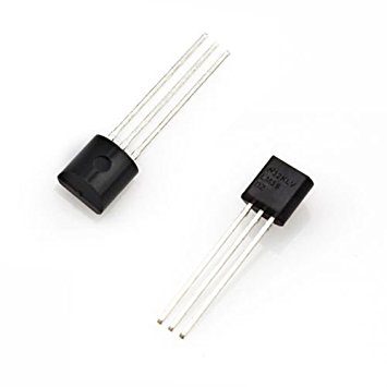
This LM35 Arduino guide uses a classic 5 V Uno-compatible board to read the sensor’s analog output. It keeps the reference-voltage assumption visible and prints a modest one-decimal result. The example is a room-temperature learning setup, not a calibrated instrument or a design for the LM35’s entire temperature range.
Verify the sensor package and supply

Identify +VS, VOUT and GND from the exact part’s datasheet, including the specified viewing direction. TI’s TO-92 package drawing is a bottom view, so do not substitute a generic front-view transistor pinout. With power removed, connect +VS to the documented 5 V supply, GND to Arduino GND and VOUT to A0. Keep the wiring short and check the board’s analog input limits.
Understand the conversion before uploading
The LM35 nominal output slope is 10 mV/°C. An estimated output of 0.250 V therefore corresponds to about 25°C. On a classic Uno using its default analog reference, the ADC code depends on the actual supply/reference voltage. A value of exactly 5.000 V in a sketch is an assumption unless you have measured or otherwise established it under the relevant conditions.
Use an explicit reference-voltage estimate
The example averages 16 raw readings and converts them using a visible ADC_REF_VOLTS constant. The 1024 divisor reflects the ideal 10-bit ADC step size used in this simple estimate. Averaging reduces some random variation but does not remove reference error, sensor offset or systematic interference.
const byte SENSOR_PIN = A0;
const float ADC_REF_VOLTS = 5.0f; // Replace with an established reference value.
void setup() {
  Serial.begin(9600);
}
void loop() {
  unsigned long total = 0;
  for (byte i = 0; i < 16; i++) {
    total += analogRead(SENSOR_PIN);
    delay(5);
  }
  float averageRaw = total / 16.0f;
  float volts = averageRaw * ADC_REF_VOLTS / 1024.0f;
  float celsius = volts / 0.010f;
  Serial.print("Estimated temperature C: ");
  Serial.println(celsius, 1);
  delay(500);
}
Interpret resolution honestly
With an ideal 5 V reference and a 10-bit ADC, one ADC step is approximately 4.88 mV, corresponding to roughly 0.49°C at the LM35 slope. Averaging can produce fractional displayed steps, but it cannot justify claiming arbitrary hundredth-degree accuracy. The one-decimal display is a formatting choice, not a certified uncertainty statement.
Check a suspicious reading in the right order
| Observation | First checks |
|---|---|
| Very high or implausible value | Pin orientation, supply, ground and correct sensor identity |
| Value near zero | Signal continuity, sensor supply and output voltage |
| Large random jumps | Floating analog input, loose ground or interference |
| Stable but offset value | Actual reference voltage and thermal placement |
| Slow response | Package contact, enclosure and airflow |
Measure the sensor output with a suitable meter if available and compare it with the ADC estimate. Do not hold a soldering iron or another uncontrolled heat source against the device to test it.
Keep the setup’s limits clear
The basic single-supply arrangement is not a complete negative-temperature measurement design. The datasheet includes other circuits for wider-range use. Long cables, capacitive loads and noisy environments also need additional design consideration. Verify the manufacturer application guidance rather than extending this short breadboard example into an industrial sensor installation unchanged.Newest in the store


Save the measurement conditions
Record the board, sensor marking, supply/reference value, wiring and approximate environment with your results. If you compare against another thermometer, allow both sensors to reach a similar stable condition and account for their placement. Do not present an arbitrary software offset as a calibration certificate. For critical measurement, use an appropriately specified and validated complete instrument.
Epro parts and availability
These are relevant Epro listings, not independent authenticity or performance certifications. Prices below were checked on 19 October 2026; they are a dated snapshot rather than a historical price implied by this article’s publication date. Confirm the exact variant, included accessories, stock and current checkout price before ordering.
| Listing | Checked price | Stock at check |
|---|---|---|
| LM35DZ Precision Centigrade Temperature Sensors 100% Orignal in Pakistan | PKR 280 | In stock |
Frequently asked questions
Does averaging make the sensor more accurate?
It can reduce some random ADC variation, but not sensor tolerance, reference-voltage error or thermal-placement bias.
Can this code be copied unchanged to ESP32?
No. ADC resolution, reference behavior and input limits differ; adapt the acquisition and conversion to the actual board.
Related Epro guides
Technical references and verification
The guidance above is based on the manufacturer documentation linked here and the listed product information. Example procedures and sketches are provided for a controlled low-voltage bench setup; no independent hands-on test of your particular board or adapter is claimed. Check the markings and documentation for your actual revision.