


FM24CL64 Arduino: 7 FM24CL64B Record Checks

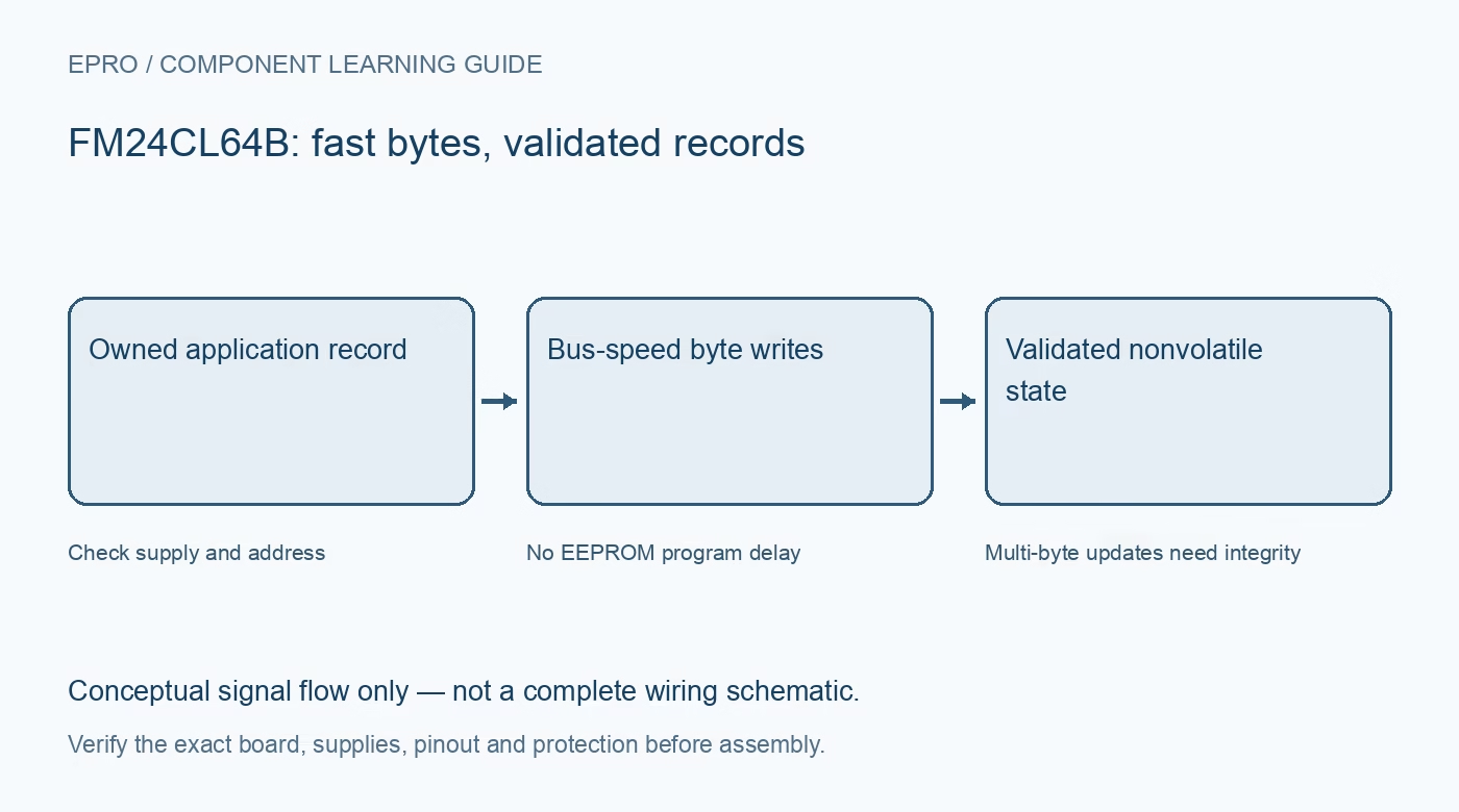
An FM24CL64 Arduino test using the FM24CL64B device should prove byte addressing and record integrity while preserving existing contents. Bus-speed nonvolatile writes are convenient, but they do not guarantee that an interrupted application record is valid. Use an owned test area and a driver appropriate to the exact B-suffix device.
FM24CL64 Arduino supply and address checks
Confirm the 2.7 V to 3.65 V operating supply, host signal levels, I2C pull-ups and address pins. Inspect whether WP is strapped or host-controlled. A five-volt Arduino connection is not safe simply because another eight-pin memory used the same header layout.
Identify an owned disposable test area
Read existing data before any test write, back up important contents and reserve a small address interval within 8192 bytes. Reject operations that would cross the array boundary rather than relying on an internal address rollover. Keep the test independent of live calibration or configuration records.
Use the proper internal address sequence
Distinguish the seven-bit I2C device address from the two-byte memory location sequence. Send the documented byte order and check return status. A driver with a one-byte location address can produce repeating or misplaced data even if the memory acknowledges every transaction.
Remove EEPROM assumptions deliberately
The device does not need a separate EEPROM programming wait after each completed byte transfer. Nor does it use EEPROM page buffering. Keep useful host-buffer chunking and error checks, but do not copy long write delays or page-wrap behavior as though they were requirements of this memory.
Compare actual stored bytes
Write a small distinctive pattern to the reserved region and read it back through a documented random or sequential read. Compare the entire payload and boundary addresses. Preserve transfer errors separately from returned data; an unavailable read is not a valid zero byte or a confirmed unchanged record.
Treat commit as an application operation
A record with several fields can be interrupted after some bytes have committed. Add a format version, length, checksum and sequence or commit mechanism appropriate to the application. A checksum detects many corruptions but does not by itself provide atomic replacement or authenticate data against deliberate modification.
Newest in the store


Test persistence and controlled recovery
Verify a completed disposable record after a valid power cycle and demonstrate that incomplete or invalid records are rejected by software. Check WP behavior using the exact protocol without overwriting unrelated addresses. Document the test conditions rather than claiming unlimited endurance, unconditional retention or power-fail-proof application behavior.
Frequently asked questions
Should an EEPROM driver’s fixed write delay be retained?
It is not required by this F-RAM’s bus-speed write mechanism, but preserve necessary host and protocol error handling.
Does a successful multi-byte transmit prove a valid application record?
Read back and validate the complete record, including its format and integrity fields.
Availability and illustration note
No matching Epro product was returned by the catalog search on 21 October 2026 UTC. This learning guide does not assert stock, a selling price or compatibility of an unidentified substitute. The illustration is an original conceptual signal-flow diagram, not a product photograph or complete wiring schematic.
Related Epro reading
For a first bench setup, review breadboard connections and continuity checks and I2C voltage-level translation. These guides do not replace the exact module schematic.
Technical references and limitations
Source: Infineon FM24CL64B serial F-RAM datasheet. Electrical limits apply to the named part, not automatically to every carrier board. This is a documentation-based learning workflow, not a claim of independent hardware testing, traceable calibration or safety certification.