


HC05 Bluetooth Module Price: 7 Buying Checks

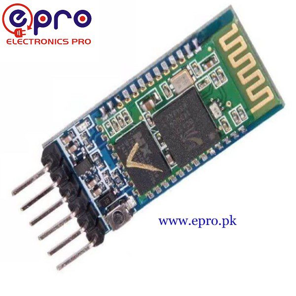
An HC05 Bluetooth module price comparison should start with the intended connection, not just the cost of a small wireless board. The common HC-05 is used as a Bluetooth Classic serial link for microcontroller projects, not as a universal replacement for every Bluetooth Low Energy peripheral.
Check the host device, supported profile, UART levels and actual breakout board before ordering. This guide does not promise a particular wireless distance, universal phone compatibility or secure control of a consequential device.

HC05 Bluetooth module price and listing scope
| Listed item | Price (PKR) | Project role |
|---|---|---|
| Bluetooth Module HC05 in Pakistan | 740 | HC-05 Bluetooth serial breakout module |
Price snapshot: Epro listings checked on 18 October 2026. Confirm the current price, availability, delivery charges and package quantity on the linked page before ordering. These are dated listing prices, not a quotation or an independent performance test.
The Epro HC05 listing describes a module with supply, ground, TX, RX and configuration/status connections. Its breakout supply specification must not be confused with the voltage allowed on the smaller radio module’s UART pins.
1. Confirm Bluetooth Classic serial support
A host needs support for the appropriate Classic serial connection, often described as SPP, and an application that can use it. A Bluetooth logo alone does not establish that the desired app or operating system provides that interface.
Check compatibility before buying for a particular phone, tablet or computer. A BLE-only app is not automatically a terminal for a Classic serial module. Do not assume an iPhone app supports a generic HC-05 serial link simply because another Bluetooth accessory works with the phone.
2. Distinguish breakout power from UART voltage
Many HC-05 carrier boards include a regulator and accept a 5 V supply at VCC, while the radio and UART remain in a 3.3 V logic domain. A bare daughterboard is not equivalent to the regulated carrier.
The HC-05 connection guide by Martyn Currey documents this distinction and uses a divider on the Arduino-to-module RX path. Confirm the supplied board’s actual arrangement rather than relying on a broad TTL-compatible label.
3. Plan crossed transmit and receive signals
A controller’s TX sends to the module’s RX, while the module’s TX sends to the controller’s RX. Both need a suitable shared ground reference. Connecting TX to TX is not a substitute for checking which endpoint sends and which receives.
Newest in the store


For a 5 V Uno, reduce the outgoing 5 V signal before it reaches a 3.3 V HC-05 RX input. The module’s regulated supply does not automatically translate that data line. Do not connect the module to traditional bipolar RS-232 voltage levels.
4. Separate data mode from command mode
Data mode passes application bytes over the link. Command mode is used for supported configuration commands. Firmware, board variants and the KEY/button arrangement affect how configuration is entered and what commands are available.
Do not assume a visible LED pattern or one quoted AT-mode baud rate proves the data-mode setting. Record known configuration values and consult the actual module documentation. Randomly changing settings can make a previously understandable link harder to diagnose.
5. Match UART speed to the configured module
A common fresh-module data-mode setting is 9600 baud, but a previously configured unit may differ. The controller UART and the HC-05 must agree. The USB Serial Monitor connection also has its own baud setting, which is a separate link.
A successful wireless pairing does not prove correct UART timing. If received characters are garbled, review speed, framing and voltage levels before blaming radio range. A simple harmless text exchange is a better first test than a motor command.
6. Treat range as an installation question
Distance depends on the actual module, antenna, host, interference, obstacles and enclosure. A catalog maximum is not a guaranteed range through walls or inside a metal box. Test the intended installation and include a reasonable margin for changing conditions.
Wireless disconnection also needs a defined application response. A demonstration terminal link is not an emergency stop or a reliable safety channel. Do not base a hazardous actuator’s continued operation solely on the last character received.
7. Budget for safe testing and configuration
Use the HC05 connection with Arduino guide to exchange non-sensitive text first. A default pairing code should not be treated as a strong security design. For a finished product, assess credential handling, access, reconnection and safe failure behaviour separately from the initial wiring exercise.