


IRLZ44N Datasheet Pinout: Gate, Drain, Source and a Small LED Test

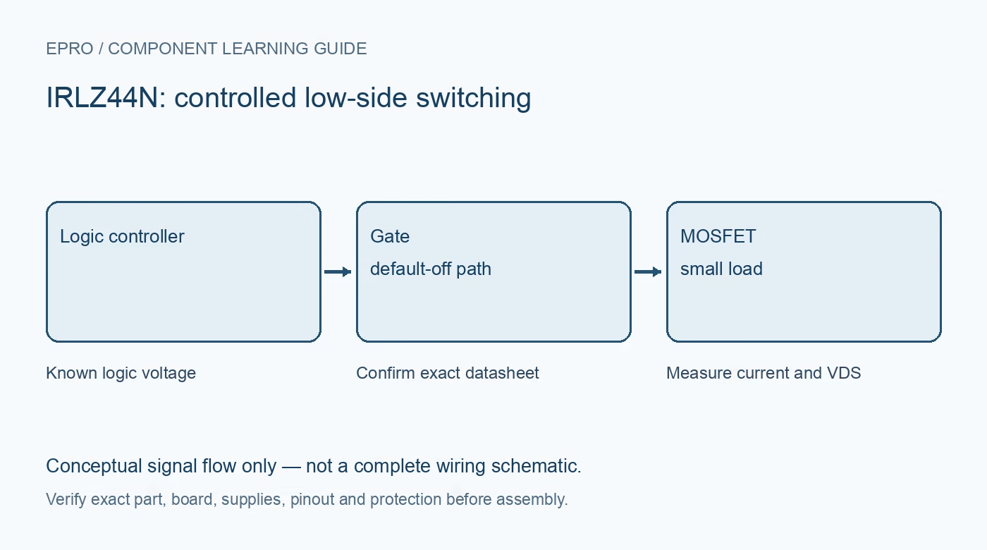
The IRLZ44N datasheet provides the package orientation needed to distinguish gate, drain and source. A small resistor-limited LED test can then check basic low-side switching without a motor, large battery or high-current load. It does not certify the part’s full ratings.
Read the package drawing in its stated view
For the referenced IRLZ44NPbF TO-220 package, the lead assignments are gate 1, drain 2 and source 3, with the tab connected to drain. Establish the drawing’s viewing direction and match the supplied manufacturer package before wiring. Do not transfer this arrangement blindly to another device or a module header.
Choose a low-energy load
For an illustrative 5 V bench setup, use a small indicator LED with a 2.2k series resistor from supply positive to the MOSFET drain, and connect source to the intended common ground. Check LED polarity and resistor value before powering. This intentionally small current is for observing basic switching, not demonstrating a power-current capability.
Define gate drive and the off state
A compatible 5 V control source can drive the gate through an illustrative 1k series resistor for a slow on/off test, with a 100k gate-to-source resistor providing a default-off path. Check the controller’s limits and the actual device specification. These example values are not a universal recommendation for fast PWM, long wires or a large load.
Inspect before enabling the control source
Use a current-limited low-voltage supply and make wiring changes with power removed. Verify source reference and that the load is not bypassing the MOSFET. Ensure the controller and supply share the required reference without creating an unintended power path. A charged floating gate can produce confusing behavior, which is why a defined off path matters.
Compare the two static states
First command low and confirm that the indicator is off. Then command high and observe the indicator while measuring gate-source voltage and the load current if suitable equipment is available. Measure drain-source voltage directly across those terminals. Meter resolution may prevent a meaningful low-resistance calculation at this small current; do not report an invented precise resistance.
Test reset before expanding
Reset or disconnect the control signal in the planned safe manner and confirm the gate returns to the intended off state. Unexpected glow or heating requires investigation of pin identity, wiring, drive or component damage. Do not replace the LED with an inductive load without redesigning suppression, wiring and thermal handling. A passing LED demonstration remains only a basic functional check.Newest in the store


Availability and illustration note
No matching product was found in the checked Epro catalog for this topic on 19 October 2026. This article therefore does not quote an Epro price or claim stock. The original illustration shows conceptual signal flow only, not a complete circuit or a photograph of a supplied product. Obtain a documented component or carrier with a known pinout and electrical specification.
Frequently asked questions
Is the metal tab electrically isolated?
Not in the referenced package: it is connected to drain. Check insulation requirements before mounting.
Does the small LED test verify maximum current?
No. It checks limited static behavior and cannot validate high-current thermal or switching performance.
Related Epro reading
Review breadboard connections before assembling a prototype. For controller expansion, the Mega 2560 pin guide explains why pin names and electrical limits must be checked together.
Technical references and test limitations
This guide uses the documentation linked below. The procedures are for a controlled, low-voltage learning setup; no independent hands-on test of the particular seller board is claimed. Record the actual part markings, wiring and firmware version before drawing conclusions from a test.