


LM2596 vs MP1584: Choosing Between Actual Buck Modules

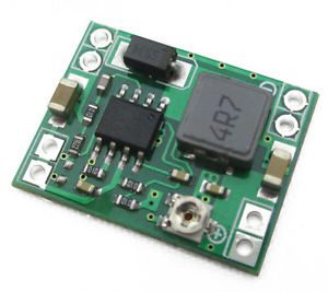
An LM2596 vs MP1584 comparison is useful only when it compares the actual boards and operating conditions. Both names commonly appear on adjustable step-down modules, but a larger board or a higher IC headline current does not establish a guaranteed continuous output for an anonymous module.
Start with the same source and target

Write down the input minimum and maximum, desired output tolerance, steady load current and startup peaks. Check each complete board’s documented limits against that same requirement. A module that works from a stable bench supply may behave differently on a weak adapter or a long input cable. Neither ordinary buck topology solves every above-and-below-input situation.
Compare board ratings rather than only chip names
The Epro MP1584 listing checked here describes a one-amp module. The MP1584 IC datasheet describes a different level of component capability under stated conditions. Apply the same discipline to LM2596 boards: verify the actual manufacturer, layout, components and seller operating envelope instead of copying the IC maximum into a module recommendation.
Consider space, adjustment and installation
Compact MP1584 boards can fit small enclosures, while many common LM2596 modules offer more physical area and larger connection pads. Those are typical board-format considerations, not universal properties of every implementation. Inspect the actual dimensions, mounting options, terminal access and trimmer location before choosing based on a product photograph.
Examine thermal behavior at the intended load
Heat depends on conversion ratio, switching and conduction losses, components, airflow and copper area. A larger footprint does not automatically mean cooler operation, and a tiny board does not automatically fail at every moderate load. Compare documented test data where available, then validate the actual board conservatively in its intended enclosure.
Compare voltage quality with a suitable method
Measure loaded output at the load terminals and check startup behavior if it matters. A multimeter can reveal DC droop but cannot fully characterize switching ripple or fast transients. Use an appropriate instrument and measurement setup before claiming one module is universally lower-noise. Keep the source, load and wiring comparable between tests.
Check protection and supply-system needs
Neither module name proves reverse-polarity protection, isolation, battery charging or independent overvoltage protection. Inspect the complete design. If the load is valuable or consequential, include appropriate protective measures and safe power-up checks. A module surviving one short experiment is not a reliability qualification.
Newest in the store


Choose the better documented fit
For a small, modest load, a correctly documented compact board may be convenient; for other needs, a board with suitable terminals, thermal margin and traceable specifications may be preferable. State the actual operating case rather than declaring one IC family universally best. The existing LM2596 adjustment guide provides additional bench-check context.
Relevant Epro listing
Product information and prices were checked on 19 October 2026. This is a current snapshot, not a historical price associated with the publication timestamp. Stock, accessories and checkout prices can change. Listing claims are not independent performance or authenticity certifications.
| Product | Checked price | Stock |
|---|---|---|
| Mini DC-DC Adjustable Step Down Buck Converter 1A MP1584 | PKR 145 | In stock |
Frequently asked questions
Which module is always better?
Neither is universally better. The complete board and actual source, load, cooling and protection requirements determine suitability.
Can I compare ripple using only a multimeter?
A DC meter does not fully characterize switching ripple or transient behavior. Use an appropriate measurement method before making that claim.
Related Epro reading
Review breadboard connections before assembling a prototype. For controller expansion, the Mega 2560 pin guide explains why pin names and electrical limits must be checked together.
Technical references and test limitations
This guide uses the documentation linked below. The procedures are for a controlled, low-voltage learning setup; no independent hands-on test of the particular seller board is claimed. Record the actual part markings, wiring and firmware version before drawing conclusions from a test.
- MP1584 manufacturer datasheet listing, hosted mirror
- TI LM2596 datasheet; verify the actual module manufacturer