


MAX485 Pinout: RS485 Signals, Supply and Selection

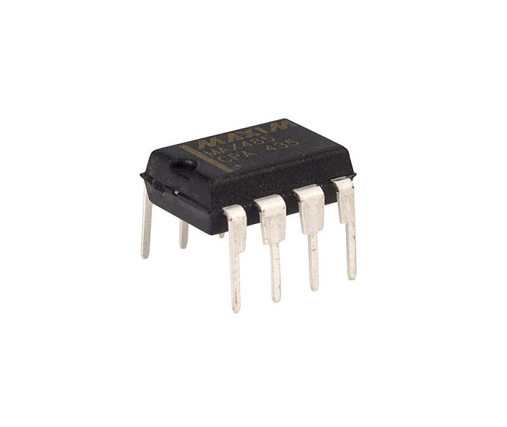
The MAX485 is a half-duplex RS485 transceiver, not a USB adapter and not a protocol controller. It translates logic-side transmit and receive signals into a differential bus interface. This guide separates its pin functions, power requirements and network wiring from higher-level protocols such as Modbus RTU.
Distinguish the bare IC from a module

The checked Epro item is a transceiver IC listing. A bare IC needs a suitable PCB or breadboard-compatible package, decoupling and the required external bus components. A ready-made module may add screw terminals, termination or bias resistors. Read the exact package and circuit rather than assuming that an IC price includes a complete communication board.
Use the correct common eight-pin map
For the manufacturer’s common DIP/SO eight-pin pinout, RO is pin 1, active-low RE pin 2, DE pin 3, DI pin 4, GND pin 5, A pin 6, B pin 7 and VCC pin 8. Confirm the package drawing and orientation before power. RO connects toward the host receive input; DI is driven from the host transmit output.
Respect the five-volt supply and signal levels
The original MAX485 operates from a single 5 V supply. Do not assume that powering a generic MAX485 board at 3.3 V is supported. The receiver output can be incompatible with a 3.3 V-only GPIO; use an appropriate interface or choose a transceiver designed for the host voltage. Check both transmit and receive directions.
Understand the direction controls
DE high enables the differential driver. Active-low RE low enables the receiver output. Half-duplex means nodes share the same pair and take turns transmitting; it is not a separate full-duplex transmit and receive pair. Firmware or an automatic-direction circuit must avoid two drivers talking at once. Define idle control states rather than leaving enable pins floating.
Design termination and bias deliberately
Use a line-style bus with termination matched to the cable at the two physical ends when required by the design. Do not add a terminating resistor at every node. Idle biasing and receiver fail-safe behavior are separate concerns; the original device’s open-input behavior does not eliminate every need for an appropriate network bias design.
Do not confuse differential signaling with isolation
A MAX485 does not provide galvanic isolation by itself. Common-mode voltage limits still matter, and a long cable between independently powered systems needs deliberate grounding, protection and potentially isolation. Keep the first experiment on a short, low-voltage bench link. Do not connect a prototype directly to industrial or building wiring based only on successful local serial text.Newest in the store


Relevant Epro listing
Product information and prices were checked on 19 October 2026. This is a current snapshot, not a historical price associated with the publication timestamp. Stock, accessories and checkout prices can change. Listing claims are not independent performance or authenticity certifications.
| Product | Checked price | Stock |
|---|---|---|
| MAX485-RS-485/RS-422 Transceiver IC in Pakistan | PKR 90 | In stock |
Frequently asked questions
Does RS485 mean Modbus?
No. RS485 describes an electrical interface. Modbus RTU is one possible protocol carried over a suitable serial link.
Is the MAX485 an isolated interface?
No. Isolation requires additional components and a suitable overall design.
Related Epro reading
Review breadboard connections before assembling a prototype. For controller expansion, the Mega 2560 pin guide explains why pin names and electrical limits must be checked together.
Technical references and test limitations
This guide uses the documentation linked below. The procedures are for a controlled, low-voltage learning setup; no independent hands-on test of the particular seller board is claimed. Record the actual part markings, wiring and firmware version before drawing conclusions from a test.