


MCP3208 ADC: 7 Reference and Acquisition Checks

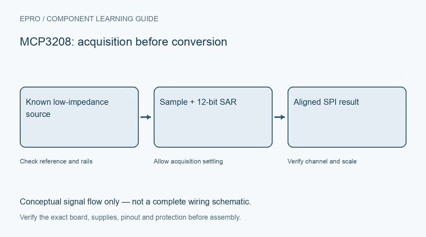
An MCP3208 adds eight multiplexed inputs and a twelve-bit SAR conversion path to a compatible host. Its external reference and sample-and-hold behavior matter as much as the channel count. Select the exact chip or carrier around a defined low-voltage signal, not a generic promise of extra analog pins.
Separate the bare IC from a carrier
The linked catalog entry describes an ADC component, not proof of a complete regulator or protected sensor board. Verify the package, pinout and required support components. Plan the analog reference, decoupling and ground return before assuming that a few jumper wires reproduce a documented evaluation circuit.
Choose a valid supply and reference
The chip supply range is 2.7 V to 5.5 V. The conversion reference is external; it is not an automatically available precision internal source. Verify reference limits, loading and noise in the datasheet. A nominal supply label alone does not establish the accuracy or stability of the resulting measurement scale.
Keep digital levels compatible
A five-volt-powered converter and a three-point-three-volt host need a logic-level assessment, especially on the converter output. Do not infer safe input voltage from the host connector shape. Use an appropriate compatible supply arrangement or documented translation while checking all control thresholds and return paths.
Account for acquisition and source impedance
The internal sample capacitor must charge through the source during a finite acquisition interval. A high-resistance divider can cause settling error even if its unloaded voltage is correct. Check source impedance and clock timing together; a buffer also needs stability, output range and acquisition-load verification.
Use the correct rate conditions
The headline 100 ksps specification applies at five volts under the documented conditions; the limit is lower at 2.7 V. Shared-bus overhead and channel sequencing reduce practical throughput. Nor should the conversion clock be slowed indefinitely: the datasheet also specifies limits associated with charge retention during conversion.
Understand pseudo-differential inputs
The differential option is not a general bipolar instrumentation input. The negative input has a narrow allowed range around analog ground, approximately plus or minus 100 mV as specified. Keep both physical inputs within their limits and use the documented channel pairings rather than arbitrary channel subtraction assumptions.
Newest in the store


Define a realistic acceptance test
At unity interpretation, one ideal code step is reference voltage divided by 4096. That is resolution, not guaranteed system accuracy. Test safe known inputs, channel order, saturation and repeatability, then document the actual reference used. A stable result does not prove calibration, isolation or suitability for mains measurement.
Frequently asked questions
Is MCP3208 interchangeable with MCP3008 software?
Not without checking the transaction and result handling: MCP3208 returns twelve-bit data, not ten-bit data.
Are eight channels sampled simultaneously?
No. The selected input is converted through one multiplexed converter.
Availability and illustration note
The catalog search on 21 October 2026 UTC returned ADC MCP3208 8 Channel 12 Bit Analog To Digital IC. Verify the exact fitted part, carrier schematic, included accessories, current price and availability before ordering; this guide does not establish compatibility from a product title alone. The illustration is an original conceptual signal-flow diagram, not a product photograph or complete wiring schematic.
Related Epro reading
For a first bench setup, review breadboard connections and continuity checks and I2C voltage-level translation. These guides do not replace the exact module schematic.
Technical references and limitations
Source: Microchip MCP3204/3208 datasheet. Electrical limits apply to the named part, not automatically to every carrier board. This is a documentation-based learning workflow, not a claim of independent hardware testing, traceable calibration or safety certification.