


MCP41010 Arduino: 7 SPI and Wiper-State Checks

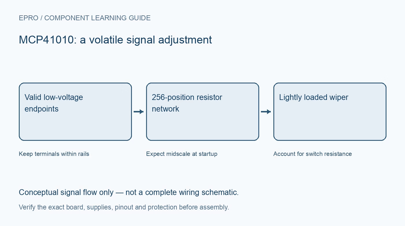
An MCP41010 Arduino experiment should show that a complete command changes a safe divider as intended. It should not treat a software variable as proof of the physical wiper state. Start with a low-voltage, lightly loaded network and verify the exact pinout before attaching another circuit.
Map the exact chip and host
Identify chip select, clock, serial input, supply, ground and the three resistor terminals from the package diagram. MCP41010 is a single-channel device without the dual family’s serial-output pin. Check the actual Arduino logic voltage rather than assuming every board has the same five-volt signaling behavior.
Configure supported SPI timing
The documented serial modes correspond to mode zero or mode three. Data enters on the specified clock edge, and chip select frames the command. Use a conservative valid clock for the supply and wiring. A pair of transmitted bytes with incorrect framing is not necessarily an accepted adjustment.
Send the command and data together
The interface uses a command byte followed by the eight-bit wiper data. Select the intended write operation and single potentiometer rather than copying dual-device channel bits without review. Complete the full sixteen-bit frame and its chip-select transition before assuming the new setting has taken effect.
Measure several safe divider settings
Apply only permitted endpoint voltages and use a suitable high-impedance measurement. Test a low code, midscale and a high code to establish direction and approximate ratio. Wiper resistance and measurement loading can prevent ideal endpoint values; do not compensate blindly before checking the actual network.
Keep software state honest
This device does not provide a normal serial wiper readback channel. A successful host transmit only establishes that software issued a request. Track the last requested code separately from a measured output, and represent an uncertain startup or interrupted transfer as unknown rather than claiming confirmed hardware state.
Handle startup before the first adjustment
After power-up the physical wiper is at midscale, even if the host remembers a different preference. Initialize control pins safely, wait for valid power and send the intended code deliberately. If midscale can produce an unsafe downstream state, the application needs hardware protection beyond a startup routine.
Newest in the store


Test recovery without stressing the device
Change a harmless software command, restore the documented write operation and confirm output movement resumes. Keep the endpoints within rails throughout. Avoid powered resistance measurements with an ohmmeter and do not use a power load as a diagnostic. Record the setup as functional integration, not calibrated resistance control.
Frequently asked questions
Why does the output change after a complete power cycle?
The wiper register is volatile and reloads midscale, not the last host-selected value.
Can the Arduino read the wiper register through MISO?
MCP41010 does not have the dual-device serial-output interface; verify state through an appropriate measurement instead.
Availability and illustration note
No matching Epro product was returned by the catalog search on 21 October 2026 UTC. This learning guide does not assert stock, a selling price or compatibility of an unidentified substitute. The illustration is an original conceptual signal-flow diagram, not a product photograph or complete wiring schematic.
Related Epro reading
For a first bench setup, review breadboard connections and continuity checks and I2C voltage-level translation. These guides do not replace the exact module schematic.
Technical references and limitations
Source: Microchip MCP41XXX/42XXX digital potentiometer datasheet. Electrical limits apply to the named part, not automatically to every carrier board. This is a documentation-based learning workflow, not a claim of independent hardware testing, traceable calibration or safety certification.