


MCP6002 Arduino: 7 Buffer and ADC-Loading Checks

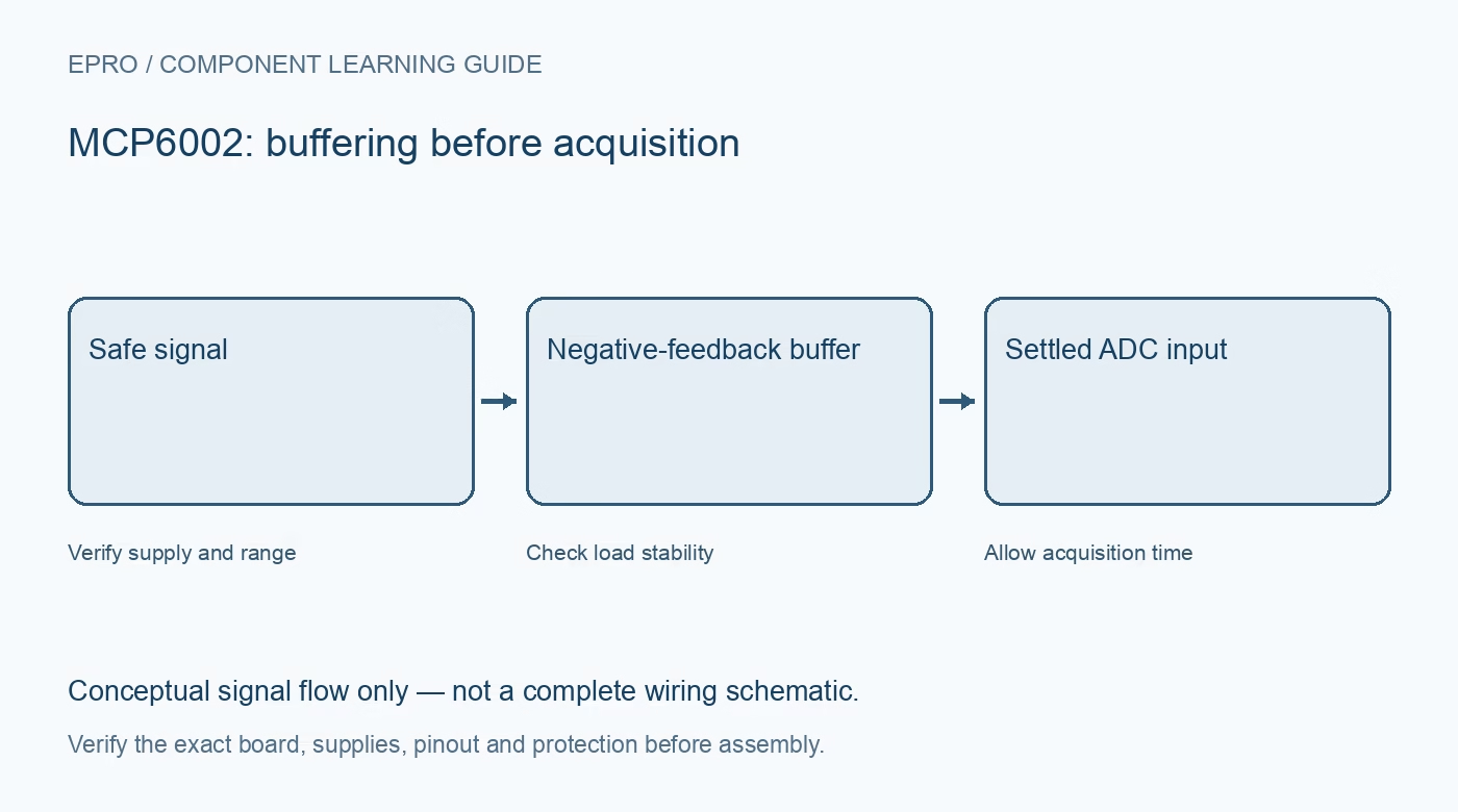
A first MCP6002 Arduino experiment should use a slow known voltage and a simple buffer before adding gain or a high-impedance sensor. Check the analog path independently from the host ADC calculation so an amplifier fault is not confused with a software scaling error.
Verify package pins and supply
Identify both amplifier channels, supply and ground from the exact drawing. Add local decoupling and use a supply within the named part’s operating range. Keep the host ADC input within its own limits even if the op amp can operate from a higher rail.
Build the intended negative-feedback path
For a voltage follower, the output returns to the inverting input and the test signal goes to the non-inverting input. Check continuity with power removed. Accidentally returning output to the positive input creates a different circuit, not a harmless alternative way to buffer the signal.
Start away from both rails
Apply a known stable mid-supply test voltage and use a light high-impedance measurement load. Confirm output and input agree within the expected error budget. Sweeping immediately to both rail endpoints can hide a feedback mistake behind clipping or make normal headroom limits appear to be failure.
Validate ADC scaling separately
Record the measured output voltage, raw ADC code and the host’s actual reference or full-scale setting. A displayed voltage derived from an assumed reference is not an independent check of the analog circuit. Verify polarity and units before adding filtering or automatic compensation.
Look for load and settling effects
Connect only the intended measurement input and account for its sampling behaviour, any cable capacitance and filter network. An isolation resistor may be appropriate under the datasheet guidance. A steady multimeter value cannot prove that the amplifier has no high-frequency oscillation or transient settling error.
Handle the second amplifier predictably
Give the unused channel a stable valid closed-loop configuration and appropriate bias rather than leaving its inputs floating. Keep feedback loops short and avoid load-current return paths through the signal reference. Do not wire an unused output directly to a rail.
Newest in the store


Increase complexity one step at a time
Only after the buffer works, introduce a documented gain network or real sensor and repeat the headroom and loading checks. Power down before rewiring. This is a functional signal-conditioning demonstration, not independent calibration, a precision voltage standard or certified protection for any downstream load.
Frequently asked questions
Why does the output stop following near a rail?
Check output swing under the actual load and supply; rail-to-rail does not mean an ideal voltage source.
Can a slow ADC log prove the buffer is stable?
No. Use appropriate timing measurement when oscillation or settling matters.
Availability and illustration note
No matching Epro product was returned by the catalog search on 21 October 2026 UTC. This learning guide does not assert stock, a selling price or compatibility of an unidentified substitute. The illustration is an original conceptual signal-flow diagram, not a product photograph or complete wiring schematic.
Related Epro reading
For a first bench setup, review breadboard connections and continuity checks and I2C voltage-level translation. These guides do not replace the exact module schematic.
Technical references and limitations
Source: Microchip MCP6001/2/4 operational amplifier datasheet. Electrical limits apply to the named part, not automatically to every carrier board. This is a documentation-based learning workflow, not a claim of independent hardware testing, traceable calibration or safety certification.