


MCP9808 Arduino: 7 Identity and Signed-Reading Checks

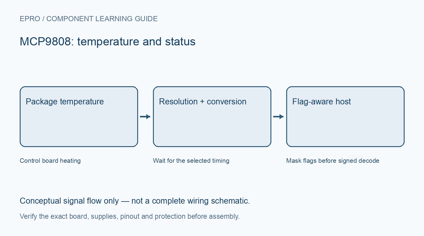
An MCP9808 Arduino test should distinguish a valid temperature from a transfer failure or a retained shutdown value. Begin with a maintained library, one documented module and stable room conditions before adding threshold outputs or automatic control.
Confirm the board wiring and pull-ups
Identify the carrier supply, ground, SDA and SCL pins from its documentation. Check host pin assignments and the bus pull-up rail without power connected. Do not assume two boards with matching connector labels use the same regulator, address straps or logic-level arrangement.
Check identity rather than acknowledgment alone
Initialize the driver at the hardware-selected address and validate the manufacturer and device identification fields using its documented revision handling. An I2C scan only proves that something acknowledged. It cannot establish that the responding component implements the expected temperature register format.
Set resolution explicitly
Choose the required resolution through the supported driver API and read it back where possible. Do not rely on a remembered reset default from a different library version or sensor family. Store the setting alongside diagnostic observations so a changed update interval has an explainable cause.
Mask flags before interpreting temperature
The ambient-temperature word contains upper status flags as well as temperature bits. A direct-register implementation must remove those flags and handle the documented sign representation. For the twelve-bit magnitude field divided by sixteen, the negative-sign case subtracts 256; it is not an arbitrary signed conversion of the entire status word.
Respect acquisition time and shutdown state
Allow the selected conversion interval after enabling measurement or changing operating state. Shutdown can leave an earlier result available to read. Reprinting that retained result with a new host timestamp must not imply that a new physical measurement occurred while conversions were stopped.
Keep threshold tests electrically simple
Read and log alert status before connecting any external load. If an alert demonstration is needed, use a logic input with a compatible pull-up and conservative thresholds around normal room conditions. Avoid heaters, dangerous temperatures and configuration locks during the first communication test.
Newest in the store


Test errors as unavailable observations
Try an incorrect address in software and require an explicit communication error rather than zero degrees. Restore the correct address and verify a new accepted reading. Log transfer success, resolution and sample age separately; a plausible number left in memory is not proof that recovery succeeded.
Frequently asked questions
Why can the upper temperature byte change near a threshold?
Status flags share the register with temperature bits and must be masked before decoding.
Is the last readable shutdown value a fresh sample?
No. Preserve its age and show that acquisition is stopped.
Availability and illustration note
No matching Epro product was returned by the catalog search on 21 October 2026 UTC. This learning guide does not assert stock, a selling price or compatibility of an unidentified substitute. The illustration is an original conceptual signal-flow diagram, not a product photograph or complete wiring schematic.
Related Epro reading
For a first bench setup, review breadboard connections and continuity checks and I2C voltage-level translation. These guides do not replace the exact module schematic.
Technical references and limitations
Source: Microchip MCP9808 datasheet. Electrical limits apply to the named part, not automatically to every carrier board. This is a documentation-based learning workflow, not a claim of independent hardware testing, traceable calibration or safety certification.