


NEO6M GPS Datasheet: Receiver Versus Breakout Board Limits

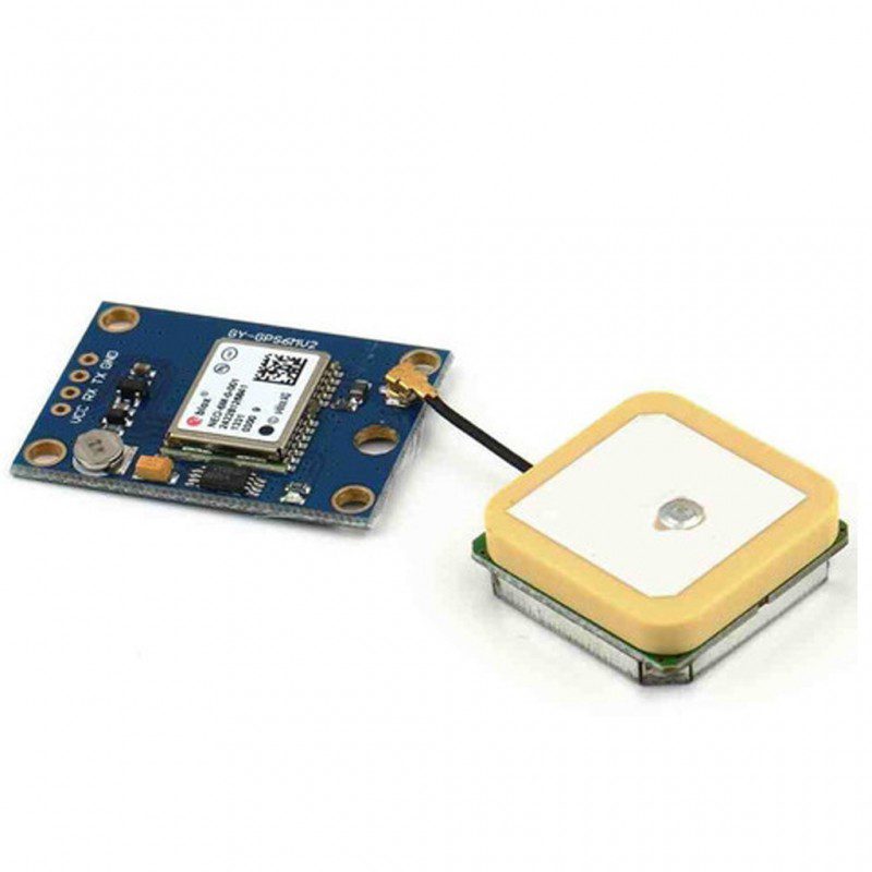
Reading the NEO6M GPS datasheet correctly means separating the u-blox receiver module from the carrier sold as a NEO6MV2 breakout. The carrier may add a regulator, antenna connector and backup components, but those additions do not make every receiver pin tolerate the carrier’s supply voltage.
Identify the actual receiver and carrier

Record the receiver marking, board revision, antenna connector and exposed header labels. The u-blox NEO-6 datasheet covers multiple receiver variants; a timing feature described for NEO-6T should not be assumed present with the same specification on NEO-6M. A catalog title or familiar shield shape is not independent proof of authenticity or exact firmware.
Keep supply and I/O specifications separate
The receiver datasheet specifies a low-voltage supply and limited input voltages. A particular carrier may accept a higher voltage through its regulator, but that is a property of the carrier input, not the bare receiver or UART. Verify the actual board documentation before using 5 V power or logic. Treat backup-power connections separately and do not improvise charging a backup cell.
Understand what the serial interface provides
The receiver has a configurable UART. The datasheet lists a default 9600-baud, eight-data-bit, no-parity, one-stop-bit setup with NMEA messages, but a previously configured board may differ. Cross TX and RX correctly and verify compatible signal levels. A GPS receiver is not a cellular transmitter and does not independently send its location to a remote dashboard.
Choose and position the antenna carefully
Confirm whether the supplied antenna arrangement is passive or active and how it is powered. Avoid damaging small RF connectors and observe ESD precautions. Begin testing with a safe open-sky view, away from severe electrical noise. A working serial stream indoors can contain no valid position because serial communication and satellite acquisition are different functions.
Read fix status rather than just coordinates
Use validity indicators, fix quality, timestamps and age of the last solution before accepting a location. Old coordinates stored by software are not proof of a current fix. Satellite count alone is not a complete accuracy guarantee. Record the test conditions and allow acquisition time without promising one fixed lock time for every antenna or environment.
Check suitability for a new design
Review the current manufacturer product status and obtain a documented source for a new commercial design. This guide does not establish current lifecycle status, authenticity, navigation safety or continued firmware support. For a learning project, a clearly documented breakout and an honest test log are more useful than an unsupported claim that every GPS board delivers the same performance.Newest in the store


Relevant Epro listing
Product information and prices were checked on 19 October 2026. This is a current snapshot, not a historical price associated with the publication timestamp. Stock, accessories and checkout prices can change. Listing claims are not independent performance or authenticity certifications.
| Product | Checked price | Stock |
|---|---|---|
| U-BLOX NEO-6M NEO6MV2 GPS Module in Pakistan | PKR 1,200 | In stock |
Frequently asked questions
Does a breakout accepting 5 V make its UART 5 V tolerant?
Not necessarily. Confirm the receiver I/O limits and the actual carrier’s level-adaptation circuit.
Will the GPS module upload a location by itself?
No. A receiver provides navigation data locally; a separate communications system is needed for a remote service.
Related Epro reading
Review breadboard connections before assembling a prototype. For controller expansion, the Mega 2560 pin guide explains why pin names and electrical limits must be checked together.
Technical references and test limitations
This guide uses the documentation linked below. The procedures are for a controlled, low-voltage learning setup; no independent hands-on test of the particular seller board is claimed. Record the actual part markings, wiring and firmware version before drawing conclusions from a test.