


PCF8523 RTC: 7 Crystal and Backup-Mode Checks

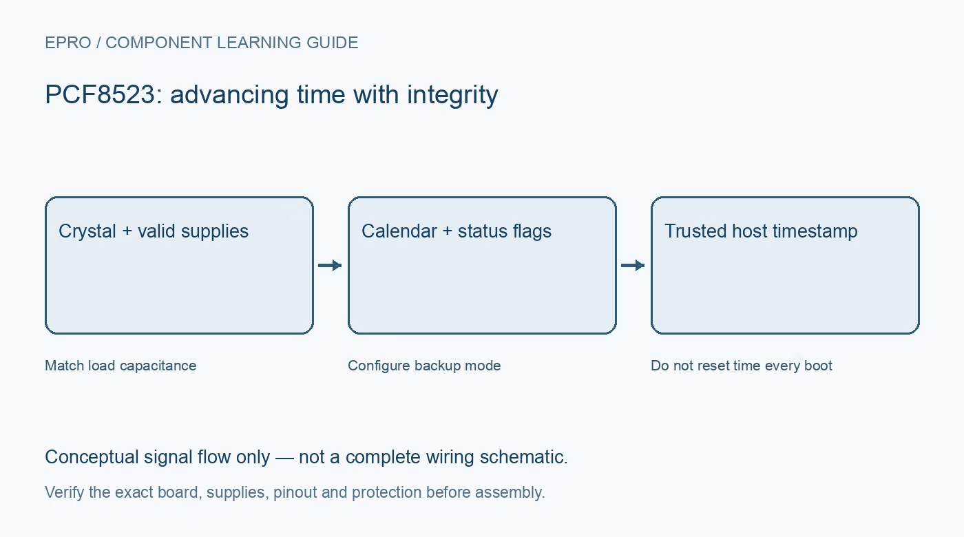
A PCF8523 tracks calendar time using a 32.768 kHz crystal and can switch to a backup supply when configured appropriately. A coin-cell holder alone does not prove that backup is enabled or time is valid. Inspect the carrier and intended power-management settings before selecting a real-time clock.
Check crystal and carrier construction
The device provides an oscillator circuit, not a universal self-contained compensated time reference. Verify the fitted crystal, routing and board cleanliness. The integrated load-capacitance choice must suit the actual crystal and layout; copying another module’s setting can introduce avoidable timing error or startup difficulty.
Distinguish timekeeping and interface voltage
The minimum voltage for maintaining clock data differs from the requirements for active I2C and power-management functions. Use the electrical table for the intended mode and temperature range, not one headline minimum. Check host logic levels and carrier pull-ups independently before connecting the bus.
Inspect the backup source safely
Identify the backup cell chemistry and any board charging or protection circuit. Do not assume a non-rechargeable coin cell can be charged safely because another RTC board used a rechargeable type. Confirm polarity and voltage and keep battery handling within manufacturer guidance rather than testing with improvised charging.
Enable the appropriate backup mode
The power-management control bits determine whether battery switchover and low-battery detection operate. The documented reset default disables switchover. A driver must configure an appropriate mode, and a backup-first startup has additional standby behavior. Do not equate an installed cell with verified backup timekeeping.
Read the oscillator-stop flag
The OS flag records an oscillator interruption and is set at power-on. A plausible date readout can still be untrustworthy if that flag indicates lost integrity. Initialization should establish trusted time before clearing the condition, and a cleared flag is not proof of absolute clock accuracy.
Budget drift instead of promising precision
Crystal tolerance, loading, temperature and aging affect timekeeping. The offset register can adjust measured frequency error, but its presence does not make the clock automatically temperature-compensated. Measure over a meaningful interval against an appropriate reference before choosing a correction or claiming a calibrated drift specification.
Newest in the store


Define a real backup acceptance test
Set a trusted time once, confirm advancing seconds and test valid main-supply removal and restoration with the intended backup mode. Read status afterward without immediately overwriting evidence. This verifies a specific assembled setup, not indefinite battery life, historical accuracy or guaranteed behavior under every power ramp.
Frequently asked questions
Will a coin cell automatically enable backup?
No. Check the power-management configuration; the documented reset default has switchover disabled.
Does the oscillator-stop flag prove the current date is correct?
No. It indicates integrity status, not that software set the correct time or timezone.
Availability and illustration note
No matching Epro product was returned by the catalog search on 21 October 2026 UTC. This learning guide does not assert stock, a selling price or compatibility of an unidentified substitute. The illustration is an original conceptual signal-flow diagram, not a product photograph or complete wiring schematic.
Related Epro reading
For a first bench setup, review breadboard connections and continuity checks and I2C voltage-level translation. These guides do not replace the exact module schematic.
Technical references and limitations
Source: NXP PCF8523 real-time clock datasheet. Electrical limits apply to the named part, not automatically to every carrier board. This is a documentation-based learning workflow, not a claim of independent hardware testing, traceable calibration or safety certification.