


TLC59711 Arduino: 7 Packet and Startup-State Checks

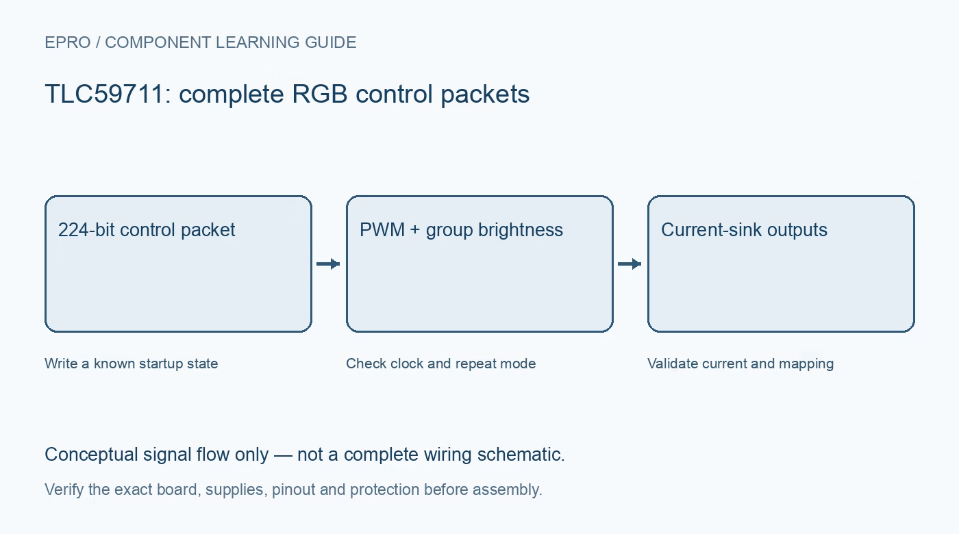
A TLC59711 Arduino test is easier to debug when startup configuration is explicit. Start with a single RGB package or modest individual LED load, verify the channel mapping and leave power scaling until the packet format and control state are understood.
Inspect supply and logic connections
Identify LED power, device power, any regulator bypass connection, ground, data and clock using the exact board schematic. Check host logic compatibility independently from the LED supply. Disconnect power before moving loads and verify the current-setting resistor before attempting a brightness test.
Use a TLC59711-specific driver
An I2C scanner will not initialize this serial interface. Select a maintained library for the exact part and actual chain length. Check which host pins or SPI-like facilities it uses and whether another device sharing those signals could see or disturb the required packet stream.
Write a complete known startup packet
The device powers up with outputs blanked, but other shift and latch contents are not all initialized to useful values. Set every function field, colour-group brightness and channel grayscale explicitly. Do not enable output based on the assumption that unspecified bytes are safely zero.
Verify command and bit ordering
Each device uses 224 bits, including the six-bit write command 0x25 and the remaining control and output data. Follow the documented most-significant-first format and chain order. Incorrect leading bits can prevent a latch update even when the host reports a successful serial transfer.
Select continuous timing intentionally
For a first demonstration, use the library’s documented internal-oscillator and repeat configuration, with blanking released only after valid data. Check the required clock-idle interval for latching. Arbitrary extra clocks or timing changes from another routine can alter what the driver accepts.
Map one physical colour at a time
Begin with small known grayscale values and conservative group brightness. Test each output index independently and record which LED colour it drives. If an entire colour group is dark, inspect brightness and wiring before increasing current or assuming every corresponding LED is defective.
Newest in the store


Test restart and explicit off states
Send a known all-off pattern, perform a controlled restart and confirm that initialization restores the intended safe state. Do not rely on a serial API return value as proof of actual LED current. Validate supply and package temperature before increasing populated channels or average brightness.
Frequently asked questions
Why can a valid-looking payload fail to update outputs?
Check the write command, complete packet length, bit order and required latch timing.
Can startup blanking replace full initialization?
No. Other data fields must still be written to known values before outputs are enabled.
Availability and illustration note
No matching Epro product was returned by the catalog search on 21 October 2026 UTC. This learning guide does not assert stock, a selling price or compatibility of an unidentified substitute. The illustration is an original conceptual signal-flow diagram, not a product photograph or complete wiring schematic.
Related Epro reading
For a first bench setup, review breadboard connections and continuity checks and I2C voltage-level translation. These guides do not replace the exact module schematic.
Technical references and limitations
Source: Texas Instruments TLC59711 datasheet. Electrical limits apply to the named part, not automatically to every carrier board. This is a documentation-based learning workflow, not a claim of independent hardware testing, traceable calibration or safety certification.