


TM1638 Module: Display, Key Scan and Serial Interface Selection

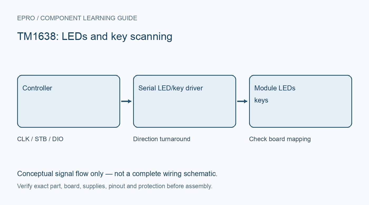
A TM1638 module combines LED display driving with key scanning through a compact serial interface. The controller’s segment and key capabilities are not the same thing as the layout fitted to every board. Check the actual digits, indicators and buttons before selecting a library or enclosure.
Separate controller capacity from board layout
The Titan Micro reference describes an LED/key controller with multiplexed display and key-scan resources. A board may fit only a subset or arrange them differently. Count the actual digits, decimal points, discrete LEDs and keys, then obtain the mapping. A library for another TM1638 carrier may initialize successfully while lighting the wrong segments.
Do not mistake the three-wire interface for I2C
TM1638 uses CLK, STB and bidirectional DIO with its own command and timing format. It is not addressed like an I2C peripheral. DIO changes direction for key reads, and the documentation specifies bit ordering and clock edges. Treating the module as a standard MOSI-only SPI device loses the returning key data.
Check supply and logic thresholds together
The referenced controller is documented around a 5 V supply and provides input-threshold requirements. A 3.3 V controller output should not be assumed to meet a guaranteed high threshold at every 5 V-powered board. Also inspect the DIO pull-up voltage before connecting it to a lower-voltage input. Use appropriate bidirectional adaptation when required.
Budget display current and brightness
The controller multiplexes the LEDs, so instantaneous segment activity and average current differ. Brightness control does not remove supply and wiring requirements. Begin with conservative brightness and avoid powering an undocumented board from an already overloaded controller regulator. Inspect the complete board’s resistor arrangement and documentation rather than deriving current from digit count alone.
Choose the library by the actual module
Look for support for the fitted display/key layout, not just the same chip name. Confirm segment ordering, digit orientation and the key bitmask returned to the application. Record the library version and settings. The TM1638 is not a substitute for a TM1637 using the same wiring and code.
Plan input behavior as well as output appearance
Key scanning reports electrical button states that still need application handling. Debounce and transition detection avoid repeating an action on every loop while a key remains pressed. Test combinations the interface actually requires, and define startup display and key states. This learning board is not a sole emergency-stop or safety-input system.Newest in the store


Availability and illustration note
No matching product was found in the checked Epro catalog for this topic on 19 October 2026. This article therefore does not quote an Epro price or claim stock. The original illustration shows conceptual signal flow only, not a complete circuit or a photograph of a supplied product. Obtain a documented component or carrier with a known pinout and electrical specification.
Frequently asked questions
Is TM1638 an I2C device because it has few signal pins?
No. Its CLK/STB/DIO interface uses the controller’s own serial commands and timing.
Will every TM1638 library match every module layout?
Not necessarily. Confirm the digit, segment, LED and key mapping supported by the library.
Related Epro reading
Review breadboard connections before assembling a prototype. For controller expansion, the Mega 2560 pin guide explains why pin names and electrical limits must be checked together.
Technical references and test limitations
This guide uses the documentation linked below. The procedures are for a controlled, low-voltage learning setup; no independent hands-on test of the particular seller board is claimed. Record the actual part markings, wiring and firmware version before drawing conclusions from a test.