


VEML7700 Light Sensor: 7 Gain and Optical Selection Checks

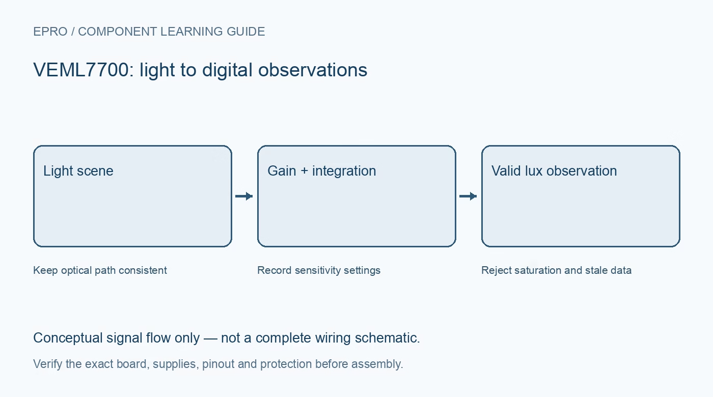
A VEML7700 measures ambient light through a configurable digital interface. Its sensitivity and bright-light range depend on settings and the installed optical path. Select the module and measurement strategy together rather than treating one advertised resolution as valid in every lighting condition.
Verify the carrier supply and bus levels
Vishay specifies a 2.5 to 3.6 V sensor supply. A carrier may add regulation, but that does not prove its data lines tolerate a 5 V pull-up. Check the board schematic, host input limits and pull-up rail before combining modules on one I2C bus.
Plan the fixed I2C address
The documented seven-bit address is 0x10. Distinguish that from shifted eight-bit read/write address bytes shown in low-level timing diagrams. If several identical sensors are needed, plan separate buses or suitable multiplexing instead of expecting an arbitrary address argument to change the hardware.
Treat gain and integration as a pair
The sensor offers gains of 1, 2, 1/4 and 1/8 with several integration times. Higher sensitivity improves low-light counts but reduces bright-scene headroom. Choose settings for the expected scene and update rate, and record the actual configuration with each diagnostic observation.
Do not combine best-case headline specifications
The finest stated resolution and the largest detectable illuminance use different settings. They are not simultaneous properties of one fixed configuration. Evaluate how the application detects saturation, changes sensitivity and waits for a valid new integration before displaying a converted lux value.
Account for the final window and orientation
Tinted plastic, a narrow enclosure opening, dust and sensor angle affect the light reaching the package. Test the final optical path with representative room lighting. A sensor that works uncovered on a bench may need a different correction or threshold after installation behind a dark lens.
Separate ALS, white-channel counts and lux
The device exposes ambient-light and white-channel data. A driver may apply setting-dependent conversion and additional bright-light correction. Read its API before choosing a calculation: raw counts, a white-channel value and a compensated lux estimate must not be presented as interchangeable quantities.
Newest in the store


Match the confidence claim to the application
A useful day/night switch or display-dimming controller does not automatically qualify as a calibrated illuminance meter. Include spectral differences, enclosure effects, data freshness and uncertainty in acceptance criteria. Do not use an unvalidated learning module as evidence of compliance with workplace lighting requirements.
Frequently asked questions
Does the finest resolution apply at maximum light level?
No. Resolution and headroom depend on gain and integration settings; compare configurations rather than combining unrelated headline limits.
Can two VEML7700 modules simply use different software addresses?
Not on one unsegmented bus when both use the fixed hardware address. Plan supported bus segmentation.
Availability and illustration note
No matching Epro product was returned by the catalog search on 21 October 2026 UTC. This learning guide does not assert stock, a selling price or compatibility of an unidentified substitute. The illustration is an original conceptual signal-flow diagram, not a product photograph or complete wiring schematic.
Related Epro reading
For a first bench setup, review breadboard connections and continuity checks and I2C voltage-level translation. These guides do not replace the exact module schematic.
Technical references and limitations
Source: Vishay VEML7700 datasheet. Electrical limits apply to the named part, not automatically to every carrier board. This is a documentation-based learning workflow, not a claim of independent hardware testing, traceable calibration or safety certification.