


TTP223 Touch Sensor Price in Pakistan: Module Mode Checks

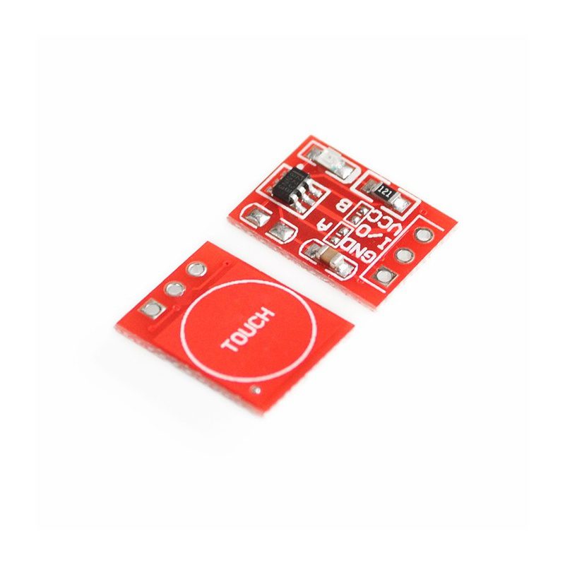
Compare TTP223 touch sensor price in Pakistan alongside the actual board modes, output voltage and electrode design. A capacitive touch module senses a change near its pad; it is not a mechanically isolated power switch. Similar-looking boards can use different chip variants, option pads and default behavior.
Check the supplied chip and board revision

TTP223 and TTP223N variants and module layouts may differ. Read the actual marking and supplier information instead of assuming every red breakout has one identical circuit. A small listing photograph may not reveal how option pads are wired. Confirm whether the purchase includes a module or only an IC.
Choose direct or toggle behavior
The referenced Tontek device supports direct mode and toggle mode through its TOG option. In direct mode output follows the detected touch state; in toggle mode successive touches change a retained logic state during operation. Board solder bridges may select these modes, but their letter labels are not universal. Inspect the actual circuit before changing a pad.
Verify active polarity
AHLB selects active-high or active-low behavior on the documented chip. A module’s indicator LED does not prove which voltage appears at its output pin. Measure or read the actual idle and touched logic states before writing an application. Software should use the observed documented polarity, not an assumption copied from a different board.
Match supply and output levels to the host
The referenced IC supports a low-voltage supply range, but board components and output logic still need checking. A module powered at five volts can present a signal unsuitable for a three-volt-only GPIO. Use a supported common-voltage arrangement or suitable interface and confirm the actual board limits.
Consider the electrode and enclosure
Pad area, overlay material and thickness, nearby wiring, grounding and environmental conditions affect sensitivity. A test through a thin plastic cover does not guarantee the same behavior through any enclosure. Metal covers and moisture can change detection substantially. Assemble and assess the intended geometry rather than using an open-board finger test as the final design proof.
Allow startup calibration and test false triggers
The documentation describes a power-on stabilization period during which the pad should not be touched. Let the assembly settle, then test repeated touches, releases and normal nearby activity. Do not install it as the sole emergency stop or safety-critical input. A capacitive input also needs application-level handling of glitches and an appropriate startup state.Newest in the store


Relevant Epro listing
Product information and prices were checked on 19 October 2026. This is a current snapshot, not a historical price associated with the publication timestamp. Stock, accessories and checkout prices can change. Listing claims are not independent performance or authenticity certifications.
| Product | Checked price | Stock |
|---|---|---|
| TTP223 Capacitive Touch Sensor Switch Button Module | PKR 55 | In stock |
| TTP223B Capacitive Touch Switch Module in Pakistan | PKR 110 | In stock |
| TTP223B Digital Touch Sensor in Pakistan | PKR 120 | In stock |
Frequently asked questions
Do all boards use the same A/B solder-pad meanings?
No such assumption is safe. Check the actual module schematic and option connections.
Can it switch a motor directly?
No. Its logic output is an input signal for a suitable controller or driver, not a motor-power switch.
Related Epro reading
Review breadboard connections before assembling a prototype. For controller expansion, the Mega 2560 pin guide explains why pin names and electrical limits must be checked together.
Technical references and test limitations
This guide uses the documentation linked below. The procedures are for a controlled, low-voltage learning setup; no independent hands-on test of the particular seller board is claimed. Record the actual part markings, wiring and firmware version before drawing conclusions from a test.