


AD9850 DDS: 7 Reference-Clock and Output Checks

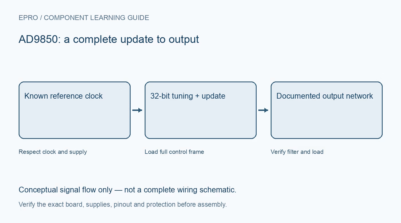
An AD9850 uses direct digital synthesis to create a clock-referenced output. The chip, oscillator and surrounding analog circuitry jointly determine what a module can deliver. Define a low-frequency wired bench use before selecting a board, and do not confuse register resolution with calibrated generator performance.
Inspect the module rather than its photograph
Identify the chip marking, oscillator, supply arrangement, output filter and any amplifier or comparator connections. Modules with similar connectors can have different output networks. Verify the exact schematic and documented input levels before relying on a generic pin diagram or supply-voltage claim from another board.
Check clock limits at the chosen supply
The headline reference-clock capability is conditional on the documented supply and operating specifications. Do not assume every lower-voltage configuration permits the same maximum clock. Read the timing and electrical tables for the exact part, oscillator and board before selecting an operating point.
Understand the frequency tuning word
The thirty-two-bit frequency word determines the output relative to the reference clock. An ideal step equals that clock divided by two to the thirty-second power. This fine increment does not remove reference tolerance, jitter, analog distortion or measurement uncertainty. Record the actual oscillator frequency used by software.
Distinguish the reference and interface clocks
The synthesis reference clock and the serial loading clock serve different purposes. Changing a host transfer rate does not directly set the generated waveform frequency. Keep the reference-clock constant and the programming interface timing separate in design notes to avoid diagnosing the wrong signal.
Identify analog and comparator outputs
The DAC current output requires its documented external network and loading. Comparator-derived outputs are separate functions, not interchangeable analog sine outputs. Check the exact labeled terminal and schematic before attaching an instrument. A digital waveform connector does not prove a calibrated amplitude or a universal fifty-ohm driver.
Plan filtering and loading together
The ten-bit DAC and reference clock produce spectral images as well as the desired signal. Reconstruction filtering and a suitable output stage determine useful waveform quality. Evaluate a modest-frequency output into a known compatible impedance rather than assuming the highest advertised output range is equally clean under every load.
Newest in the store


Limit claims to a measured wired setup
A board that accepts a frequency command is not automatically calibrated, isolated or compliant for intentional radio transmission. Use a wired protected bench connection without an antenna, and inspect frequency, amplitude, offset and unwanted components separately. Independent verification is needed before using it as a reference for another instrument.
Frequently asked questions
Does 32-bit frequency tuning mean 32-bit analog amplitude?
No. The frequency accumulator and ten-bit DAC describe different parts of the device.
Is AD9850 interchangeable with AD9851 configuration?
Do not assume so. Verify the exact device control format and reference-clock behavior.
Availability and illustration note
No matching Epro product was returned by the catalog search on 21 October 2026 UTC. This learning guide does not assert stock, a selling price or compatibility of an unidentified substitute. The illustration is an original conceptual signal-flow diagram, not a product photograph or complete wiring schematic.
Related Epro reading
For a first bench setup, review breadboard connections and continuity checks and I2C voltage-level translation. These guides do not replace the exact module schematic.
Technical references and limitations
Source: Analog Devices AD9850 datasheet. Electrical limits apply to the named part, not automatically to every carrier board. This is a documentation-based learning workflow, not a claim of independent hardware testing, traceable calibration or safety certification.