


DS3502 Digital Pot: 7 Bias and EEPROM Checks

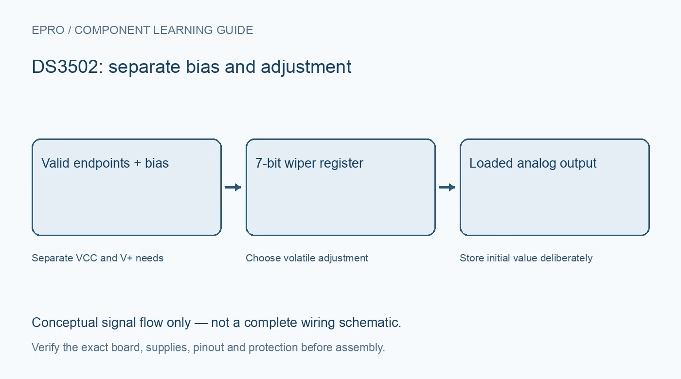
A DS3502 combines a seven-bit digital potentiometer with a nonvolatile initial setting and I2C control. Its higher-voltage analog capability does not make the logic interface or wiper a power output. Review the exact carrier and separate bias requirements before selecting it for a low-energy signal adjustment.
Separate logic supply from analog bias
VCC powers the control interface and has a specified 2.5 V to 5.5 V range. V+ is a separate wiper-bias supply with its own requirements, including its relationship to VCC. A three-point-three-volt host supply alone is not evidence that an unidentified bare-chip wiring arrangement supplies every required pin correctly.
Read normal limits rather than absolute maxima
The documented higher analog voltage range is conditional on valid V+ bias and pin limits. Do not apply that voltage to SDA, SCL or address pins. Start with a manufacturer-supported low-voltage arrangement and inspect any carrier bias circuitry before introducing a separate analog source.
Include loading and wiper resistance
The network is nominally ten kilohms with 128 positions, but the wiper resistance is significant and the current rating is limited. A lightly loaded divider behaves differently from a low-resistance load. Check specifications at the actual bias and setting; it is not a motor control resistor or a buffered laboratory voltage source.
Distinguish output code from calibrated voltage
Codes zero through 127 select the wiper along the resistor network. The ideal divider calculation depends on both endpoint voltages and the code, while endpoint error and loading affect the real result. A seven-bit setting is neither an exact resistance nor a traceable voltage calibration.
Understand the power-up initial value
On power-up the nonvolatile initial-value register is copied into the active wiper register. That permits a saved starting position, but software must still verify whether the stored choice suits the connected circuit. The initial setting is not a universal fail-safe state or confirmation of successful live communication.
Control EEPROM writes intentionally
The control register powers up in a mode where writes to the wiper address also update the nonvolatile initial value. Selecting volatile-only mode allows repeated live adjustments without those EEPROM writes. Finite endurance and write-cycle timing make this an important design decision, not a minor library implementation detail.
Newest in the store


Plan a documented acceptance sequence
Verify the address straps, compatible I2C pull-ups, bias rails and output load before testing. Compare several modest divider settings, then separately test an intentionally saved startup value. Treat this as a documentation-based integration exercise, not proof of isolation, precision output performance or compatibility with every DS3502-labelled module.
Frequently asked questions
Can the analog voltage rating be applied to I2C pins?
No. The logic interface has its own VCC-related voltage limits.
Should every live adjustment update EEPROM?
Usually not. Use the documented volatile-only mode for repeated adjustments and save deliberately when needed.
Availability and illustration note
No matching Epro product was returned by the catalog search on 21 October 2026 UTC. This learning guide does not assert stock, a selling price or compatibility of an unidentified substitute. The illustration is an original conceptual signal-flow diagram, not a product photograph or complete wiring schematic.
Related Epro reading
For a first bench setup, review breadboard connections and continuity checks and I2C voltage-level translation. These guides do not replace the exact module schematic.
Technical references and limitations
Source: Analog Devices DS3502 datasheet. Electrical limits apply to the named part, not automatically to every carrier board. This is a documentation-based learning workflow, not a claim of independent hardware testing, traceable calibration or safety certification.