


IRLZ44N MOSFET: Logic-Level Drive Still Needs Electrical Checks

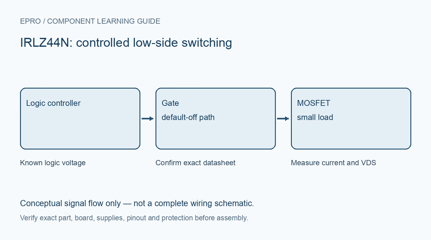
IRLZ44N is a logic-level N-channel MOSFET, but that description does not remove the need to match gate voltage, current, heat and switching speed. Use the exact manufacturer datasheet and read the resistance conditions rather than choosing from the largest current number on the first page.
Use the complete part designation
Check the actual marking and manufacturer, including the N suffix and package. IRLZ44N, IRLZ44 and IRFZ44N are not interchangeable names for one identical device. A listing or an anonymous drawing is not enough to establish the supplied part’s specifications or authenticity. Keep the matching datasheet with the project record.
Read guaranteed gate-voltage conditions
The linked IRLZ44NPbF document gives maximum on-resistance values at specified 10 V, 5 V and 4 V gate-source test conditions. These support a different assessment from a part specified only at 10 V. They do not create a guaranteed resistance specification at every lower gate voltage, including 3.3 V. Check an appropriate guaranteed condition for the actual controller or choose a better fit.
Do not size the circuit from threshold voltage
Threshold is measured at a small test current and is not a recommended drive setting. The relevant switch behavior includes on-resistance at temperature, available gate drive and dynamic losses. Typical curves help explain trends but should not be treated as worst-case guarantees for an unknown part.
Account for the thermal path
The headline current rating assumes particular conditions, including controlled case temperature. A loose TO-220 part on a breadboard does not meet those conditions. Conduction loss rises with current and resistance, and junction temperature depends on package, mounting, heatsink and airflow. Check safe operating area and transient events as well as steady-state dissipation.
Keep the gate controlled during reset
Provide a defined gate-to-source off state rather than allowing the gate to float when the controller starts or disconnects. Select the drive path to suit the controller limits and intended switching rate. Gate capacitance and charge matter for PWM even when DC gate current is small. A high-current load may require a dedicated driver instead of direct GPIO drive.
Treat inductive energy and tab connections seriously
Check the exact gate, drain and source arrangement and the electrically connected metal tab before mounting. Use appropriate insulation where a heatsink must not share the drain potential. Motors and coils need suitable suppression and a deliberate power-return layout. Validate a small current-limited low-voltage circuit before increasing energy; do not use this selection discussion as a high-power construction approval.Newest in the store


Availability and illustration note
No matching product was found in the checked Epro catalog for this topic on 19 October 2026. This article therefore does not quote an Epro price or claim stock. The original illustration shows conceptual signal flow only, not a complete circuit or a photograph of a supplied product. Obtain a documented component or carrier with a known pinout and electrical specification.
Frequently asked questions
Is logic-level a guarantee at 3.3 V for every load?
No. Verify a guaranteed resistance condition at the actual gate voltage or select a device specified for it.
Is IRLZ44 the same exact part as IRLZ44N?
No. Use the full designation and matching manufacturer datasheet instead of assuming identical specifications.
Related Epro reading
Review breadboard connections before assembling a prototype. For controller expansion, the Mega 2560 pin guide explains why pin names and electrical limits must be checked together.
Technical references and test limitations
This guide uses the documentation linked below. The procedures are for a controlled, low-voltage learning setup; no independent hands-on test of the particular seller board is claimed. Record the actual part markings, wiring and firmware version before drawing conclusions from a test.