


MCP23008 I2C Expander: 7 Direction and Capture Checks

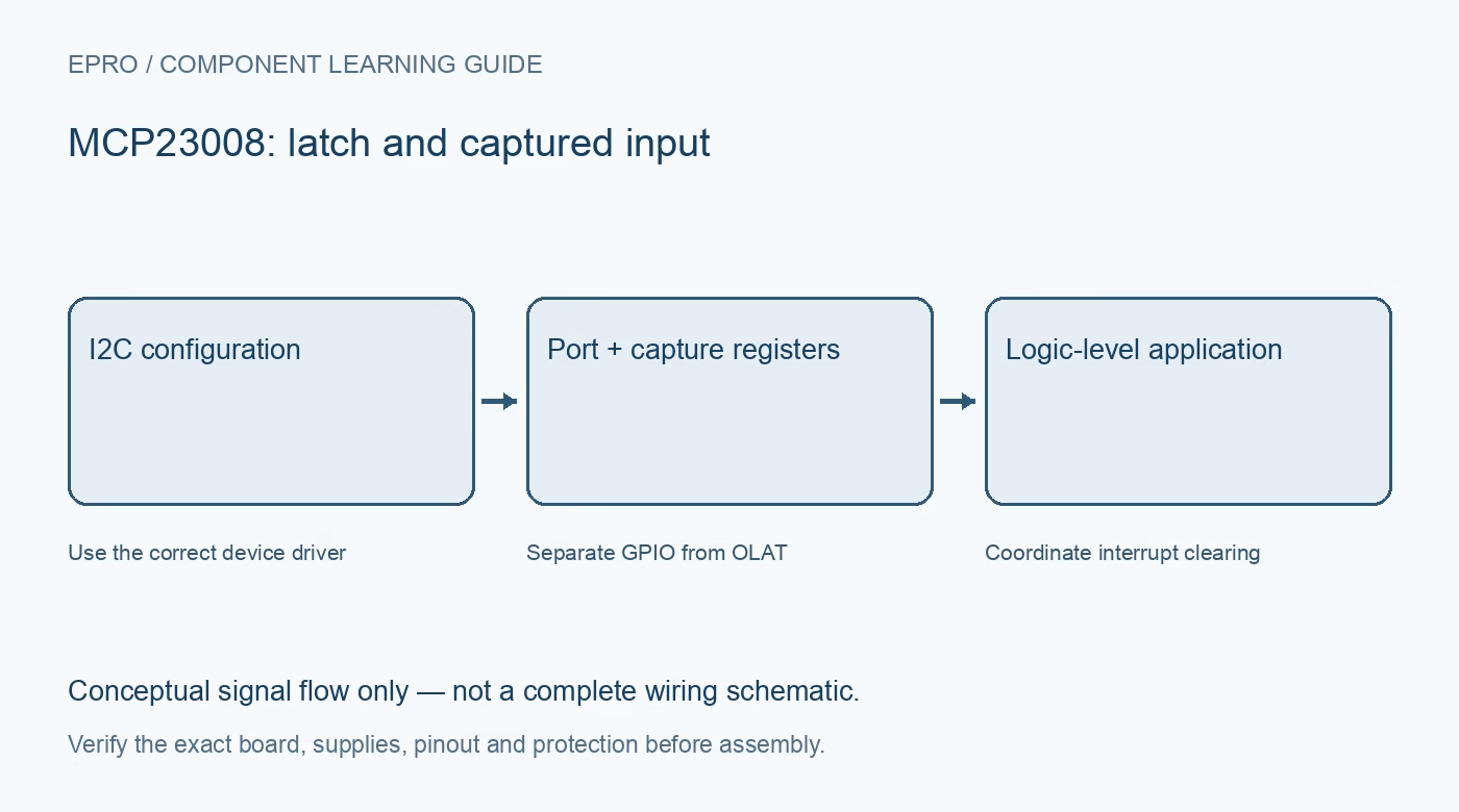
An MCP23008 provides a compact serial port expander with explicit direction and latch registers. It is not a transparent replacement for every eight-bit I2C expander. Check the current manufacturer restrictions and driver behaviour before allocating buttons, LEDs or an interrupt wire.
Read the current GP7 restriction
The referenced revision I instructs MCP23008 users to configure IO7 as output through I2C. Do not allocate GP7 as a button input because an older tutorial treats all eight positions identically. Check the current datasheet for the exact fitted part and use supported inputs for sensing.
Choose the correct interface variant
MCP23008 is the I2C variant; MCP23S08 uses SPI. Similar package pin arrangements do not make their bus protocols interchangeable. Verify the device marking and library interface before deciding that missing acknowledgments are caused by address jumpers or a damaged board.
Check direction and pull-up requirements
IODIR controls supported input and output functions, while GPPU controls weak input pull-ups. A reset default is not a complete application configuration. Unconnected supported inputs need defined levels, and pull-ups must suit the switch arrangement and environment rather than being treated as noise immunity guarantees.
Keep GPIO separate from OLAT
Reading GPIO observes pin levels; reading OLAT observes stored output commands. Writing GPIO also changes the output latch. This difference matters when a load pulls a pin away from its intended level or when software tries to preserve some outputs while changing others.
Plan reset and hardware addresses
Three address straps support multiple devices, but identical physical settings still cause a conflict. Give reset a documented stable connection and inspect carrier pull-ups before sharing a bus. Do not leave hardware configuration to assumptions drawn from a different manufacturer’s breakout.
Understand what an interrupt captures
The interrupt facility can compare against prior pin state or configured defaults. INTCAP preserves the captured condition until clearing, but is not a timestamped queue of all transitions. GPIO or INTCAP reads affect clearing, so background polling can change event-handling behaviour.
Newest in the store


Respect the output power budget
GPIO outputs are limited logic drivers, not a substitute for a relay or motor driver. Check aggregate current and allowed voltage drop as well as each pin limit. Begin with a resistor-limited LED or logic input, and provide a separate protected power stage for substantial loads.
Frequently asked questions
Is GP7 a supported button input in the referenced current documentation?
No. The cited MCP23008 revision requires IO7 to be configured as output.
Is MCP23008 register-compatible with a PCF8574 example?
No. Use a driver and initialization sequence intended for the MCP23008.
Availability and illustration note
No matching Epro product was returned by the catalog search on 21 October 2026 UTC. This learning guide does not assert stock, a selling price or compatibility of an unidentified substitute. The illustration is an original conceptual signal-flow diagram, not a product photograph or complete wiring schematic.
Related Epro reading
For a first bench setup, review breadboard connections and continuity checks and I2C voltage-level translation. These guides do not replace the exact module schematic.
Technical references and limitations
Source: Microchip MCP23008/MCP23S08 datasheet, revision I. Electrical limits apply to the named part, not automatically to every carrier board. This is a documentation-based learning workflow, not a claim of independent hardware testing, traceable calibration or safety certification.