


PC817 Circuit Diagram: A Low-Voltage Input and Output Test

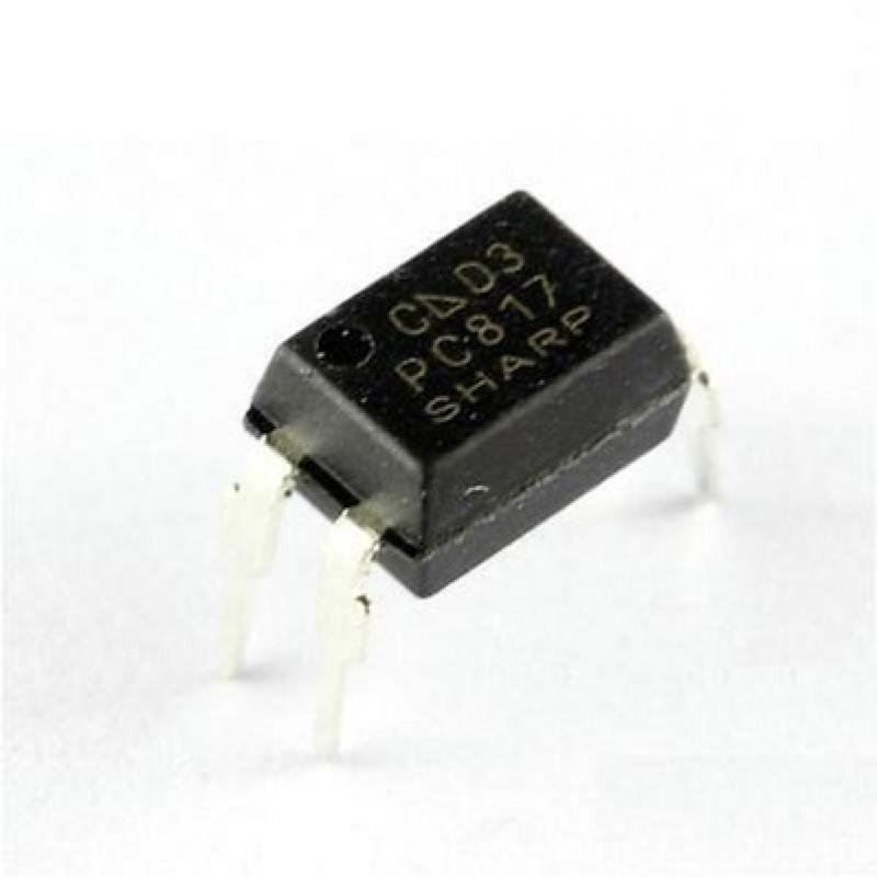
This PC817 circuit diagram describes a simple low-voltage functional test with an LED input and a pulled-up transistor output. It is not a certified isolation test or a mains interface. Verify the exact optocoupler pinout and use separately identified input-side and output-side references.
Set up the input as an LED circuit

Connect a supported low-voltage source through a calculated series resistor to the LED anode, with the cathode returning to the input-side ground. For a purely illustrative calculation, 5 V minus an assumed 1.2 V LED drop across 1 kohm gives about 3.8 mA. Check the actual device forward-voltage limits and source capability rather than treating that calculation as a universal guaranteed current.
Build a lightly loaded transistor output
Connect the emitter to the receiving side’s local ground. Pull the collector up to that side’s supported logic supply, for example with a conservative test resistor selected against the actual CTR and receiver requirements. Measure collector voltage relative to the output-side ground. Do not connect a load that requires more current than the optocoupler can reliably sink.
Read the conceptual connection map
Input side: source → series resistor → pin 1 anode; pin 2 cathode → input return. Output side: local logic supply → pull-up → pin 4 collector; pin 3 emitter → output return. The collector junction is the measured output. This is a functional topology, not a complete safety-reviewed PCB layout.
Check inactive and active states
With no LED current, the output pull-up should produce a valid high under the circuit’s loading conditions. With the intended LED current, the collector should move toward a valid low. Measure both levels and compare them with the receiving input thresholds. The circuit inverts the signal, which must be reflected in software or downstream logic.
Diagnose a weak or unchanged low state
Check LED polarity, resistor value, actual input current, collector/emitter orientation and output pull-up load. CTR may be lower than a typical value copied from a different grade. Do not short out the input resistor to make the transistor switch harder. Use the device limits and redesign the load or drive appropriately.
Keep test equipment from changing the circuit
A USB connection or an earth-referenced instrument can join the two sides through an unexpected path. That may defeat a claimed isolation boundary even though the output still changes. For this low-voltage functional test, label any shared references honestly. Do not claim galvanic-isolation verification from an ordinary continuity check or a successful LED toggle.
Newest in the store


Add timing tests only when the application needs them
If the signal changes quickly, measure rise/fall behavior with a suitable setup and the actual pull-up and receiver capacitance. Saturating the transistor deeply can affect release time. A slowly toggled bench input does not validate a communications rate. Choose a faster suitable isolator when the required interface cannot be supported conservatively.
Relevant Epro listing
Product information and prices were checked on 19 October 2026. This is a current snapshot, not a historical price associated with the publication timestamp. Stock, accessories and checkout prices can change. Listing claims are not independent performance or authenticity certifications.
| Product | Checked price | Stock |
|---|---|---|
| PC817 Optocoupler | PKR 12 | In stock |
Frequently asked questions
Why is the output low when the input LED is on?
The illuminated phototransistor sinks the pulled-up collector node, giving an inverted signal.
Can I remove the input resistor if switching is weak?
No. Measure the current and redesign within the device and source limits; the LED must remain current limited.
Related Epro reading
Review breadboard connections before assembling a prototype. For controller expansion, the Mega 2560 pin guide explains why pin names and electrical limits must be checked together.
Technical references and test limitations
This guide uses the documentation linked below. The procedures are for a controlled, low-voltage learning setup; no independent hands-on test of the particular seller board is claimed. Record the actual part markings, wiring and firmware version before drawing conclusions from a test.