


TMP117 Precision Sensor: 7 Accuracy and Integration Checks

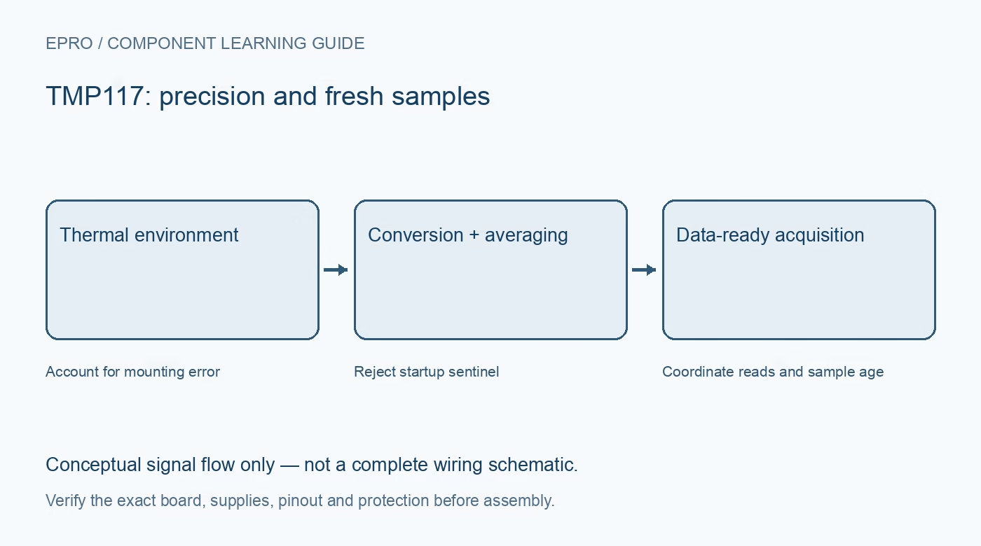
A TMP117 combines fine digital resolution with tightly specified accuracy over a defined temperature interval. The complete board still needs appropriate power, thermal placement and data handling. Choose it for a stated measurement requirement, not as an automatic certification for the finished instrument.
Keep the accuracy interval visible
The referenced datasheet specifies maximum error of 0.1 degrees Celsius from minus 20 to 50 degrees under its stated conditions. Wider operating intervals have different limits. Do not extend the narrow-band specification to every temperature or assume it includes enclosure and mounting errors.
Separate the output step from uncertainty
The signed sixteen-bit result uses 0.0078125 degrees Celsius per count. This fine step helps digital representation but does not eliminate physical measurement uncertainty. A dashboard with many decimal places can look precise even when board heating dominates the error budget.
Check temperature-dependent supply conditions
The minimum recommended supply depends on operating temperature in the datasheet. Confirm the rail against the actual intended range rather than quoting one minimum for all conditions. Verify the carrier and host bus levels independently, especially when several modules share pull-ups.
Choose averaging and update interval together
Averaging combines multiple conversions and changes active acquisition time. The default-style eight-conversion average and a one-second cycle are not eight independent displayed readings per second. Plan sample freshness, response time and power consumption with both averaging and conversion-cycle settings recorded.
Place the package for the desired temperature
Heat flows through the board, air and enclosure. A precision sensor close to a processor can accurately report the wrong location for a room-monitoring goal. Review copper connections, mechanical mounting and settling time before assigning a calibration offset to an unexplained temperature difference.
Treat stored offsets and EEPROM carefully
A programmable offset is not evidence of a traceable reference measurement. Nonvolatile storage also has defined procedures and finite endurance. Avoid routine writes in a logging loop, and preserve the manufacturer’s traceability-related storage rather than repurposing undocumented locations.
Newest in the store


Avoid unsupported instrument claims
Component specifications can support a system design, but the assembled device still needs validation for its intended purpose. This documentation-based guide does not establish medical suitability, regulatory compliance or an independent safety function. Keep those claims separate from a successful room-temperature demonstration.
Frequently asked questions
Does a fine digital step prove the whole board is accurate to that step?
No. Component error limits, thermal gradients and the reference method all contribute uncertainty.
Should a stored offset be adjusted until two boards agree?
Not without a suitable reference and stable conditions; agreement alone does not establish accuracy.
Availability and illustration note
No matching Epro product was returned by the catalog search on 21 October 2026 UTC. This learning guide does not assert stock, a selling price or compatibility of an unidentified substitute. The illustration is an original conceptual signal-flow diagram, not a product photograph or complete wiring schematic.
Related Epro reading
For a first bench setup, review breadboard connections and continuity checks and I2C voltage-level translation. These guides do not replace the exact module schematic.
Technical references and limitations
Source: Texas Instruments TMP117 datasheet. Electrical limits apply to the named part, not automatically to every carrier board. This is a documentation-based learning workflow, not a claim of independent hardware testing, traceable calibration or safety certification.