


PAM8403 Amplifier Board: Supply, Speakers and Honest Power

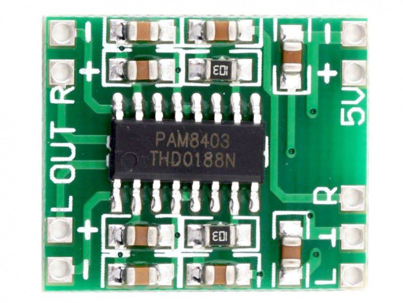
A PAM8403 amplifier board can drive a small pair of speakers from a low-voltage supply. Choosing one requires understanding its bridge outputs and the conditions behind its power rating. It is not a Bluetooth receiver or MP3 player unless the particular finished product adds those separate functions.
Read the power figure with its conditions

The Diodes datasheet specifies 3 W output at 10% THD into a 4 ohm load with a 5 V supply. That is not a promise of three watts of clean audio per channel from every USB source. Lower supply voltage, a different load, clipping limits and board losses change the useful result.
Use a supported low-voltage supply
The IC’s recommended supply range is 2.5–5.5 V, while the complete board may have its own restrictions. Never connect a 12 V adapter merely because another audio module accepts it. Check the actual voltage at the board under load and use suitable current capability. A connector’s shape does not establish supply polarity or voltage.
Choose an appropriate speaker load
Use speakers compatible with the actual module documentation and their intended acoustic enclosure. Impedance and power handling are different specifications. A larger printed wattage on a speaker does not force the amplifier to produce that power, and a lower impedance is not a safe shortcut to more volume. Start with a conservative, documented load.
Keep bridge speaker outputs separate
Each speaker connects across its own channel’s positive and negative output. Neither negative speaker terminal is a common ground, and the left and right negatives must not be joined. Do not connect ordinary common-ground headphones to the bridge outputs. Combining channels or adding an external grounded amplifier requires a properly designed interface, not a simple wire splice.
Check input and volume-control arrangements
The basic board needs an appropriate audio source; it does not decode files or pair with a phone by itself. Check whether the chosen module includes a potentiometer, input coupling and accessible mute/shutdown controls. Begin with low source volume and low amplifier volume. Excessive input level can clip even before the desired listening level is reached.
Plan layout and acceptance testing
Keep speaker leads and switching currents away from sensitive input wiring, use a stable supply and mount the board so it cannot short against an enclosure. Test one channel at low volume first, then the second. Listen for distortion and investigate abnormal heating or supply droop. A quiet bench test is not an independent validation of every seller claim about noise or efficiency.Newest in the store


Relevant Epro listing
Product information and prices were checked on 19 October 2026. This is a current snapshot, not a historical price associated with the publication timestamp. Stock, accessories and checkout prices can change. Listing claims are not independent performance or authenticity certifications.
| Product | Checked price | Stock |
|---|---|---|
| PAM8403 DC 5V Class D Mini Digital Amplifier Board Module in Pakistan | PKR 70 | In stock |
| PAM8403 Mini 5V 2 Channel Digital USB Amplifier Board GF1002 in Pakistan | PKR 140 | In stock |
Frequently asked questions
Can the two speaker negatives share ground?
No. The bridge outputs are driven nodes and must not be tied together or to ground.
Does PAM8403 include Bluetooth?
The amplifier IC does not. A separate receiver or a finished board that explicitly includes one is required.
Related Epro reading
Review breadboard connections before assembling a prototype. For controller expansion, the Mega 2560 pin guide explains why pin names and electrical limits must be checked together.
Technical references and test limitations
This guide uses the documentation linked below. The procedures are for a controlled, low-voltage learning setup; no independent hands-on test of the particular seller board is claimed. Record the actual part markings, wiring and firmware version before drawing conclusions from a test.